Just a quick note on grease...I use enough to where it squeezes out the sides of the device when I tighten the screw. People seem to lose sight of the fact that it's a fluid--it will migrate. Use the proper torque and it will expel the unneeded grease. The stuff's not that expensive, so be sure to use enough to get the job done.
If you think I'm overdoing it, look at some of the pictures of Nelson's gear. He's even more generous than I am. Mind you, he's built...oh, I dunno...at least five or ten amps in the last few years. Maybe as many as a dozen. (Ahem...) You'd think he'd have figured out if he was using too much grease.
A word to the wise: Spend less time worrying about using too much grease and a little more time buying bigger heatsinks. It'll be to your benefit.
That's a promise.
Grey
P.S.: You know how much time I spend calculating all these thermal things? Zero. Donut. Nada.
I just throw big heatsinks into the pot and stir. Somehow or another the temperature always seems to work out pretty well.
Granted, some of this is a matter of experience--the ability to heft a heatsink and visualize how much heat it can handle. But the thing that never ceases to amaze me is how people spend hours...days...weeks calculating, only to add to the ever-increasing number of posts wherein the builder says that his amp runs hot. What's wrong? I don't claim to know.
One of the big heatsink manufacturers (Aavid? I can't remember at the moment.) has an online calculator that will allow you to estimate how hot their heatsinks will run with X inches of heatsink and Y Watts of heat. Even if you're not using their heatsinks, you can usually find one of their heatsinks that has a similar profile to yours. Frequently they're nearly identical.
Find it. Use it. It's goofy to keep building amps that run hot.
I would appreciate estimates for the voltage gain of the Aleph-X when the two feedback loops are closed with the RCs, vs. the voltage gain when the two feedback loops are open.
Thanks.......I'm a bipolar X-man and have been designing emphasizing increasing local stage feedback over global feedback, and current gain over voltage gain.
Thanks.......I'm a bipolar X-man and have been designing emphasizing increasing local stage feedback over global feedback, and current gain over voltage gain.
Hi Guys,
I made washers out of channel. It brought the mounting screw down to about 97C. Heatsink is still at about 58C.
This amp sounds wonderful.
Blessings, Terry
I made washers out of channel. It brought the mounting screw down to about 97C. Heatsink is still at about 58C.
This amp sounds wonderful.
Blessings, Terry
Terry
I have parts for two Aleph X lined up but with the KSA clone just finished I am wondering if it worthwhile building this amp ?
Does the amp sound better than the KSA clone you build
Jozua
Cape Town
South Africa
I have parts for two Aleph X lined up but with the KSA clone just finished I am wondering if it worthwhile building this amp ?
Does the amp sound better than the KSA clone you build
Jozua
Cape Town
South Africa
Terry,
That is a hefty looking heat spreader between your transistors and heat sinks. How did you prepare the interface between the two? There should be grease there and preferably well flattened nearly polished surfaces. That interface resistance could be causing the temperature rise from the fins to the devices.
IIRC, when you tested you had just a few degrees rise. My guess is you weren't using the spreader then. You might be better off remotely mounting your outputs near the center of each sink without that extra mechanical junction and its thermal resistance to deal with.
BobEllis said:Terry,
That is a hefty looking heat spreader between your transistors and heat sinks. How did you prepare the interface between the two? There should be grease there and preferably well flattened nearly polished surfaces. That interface resistance could be causing the temperature rise from the fins to the devices.
IIRC, when you tested you had just a few degrees rise. My guess is you weren't using the spreader then. You might be better off remotely mounting your outputs near the center of each sink without that extra mechanical junction and its thermal resistance to deal with.
Hi Bob.
To be honest, I don't have clue what you are referring to.
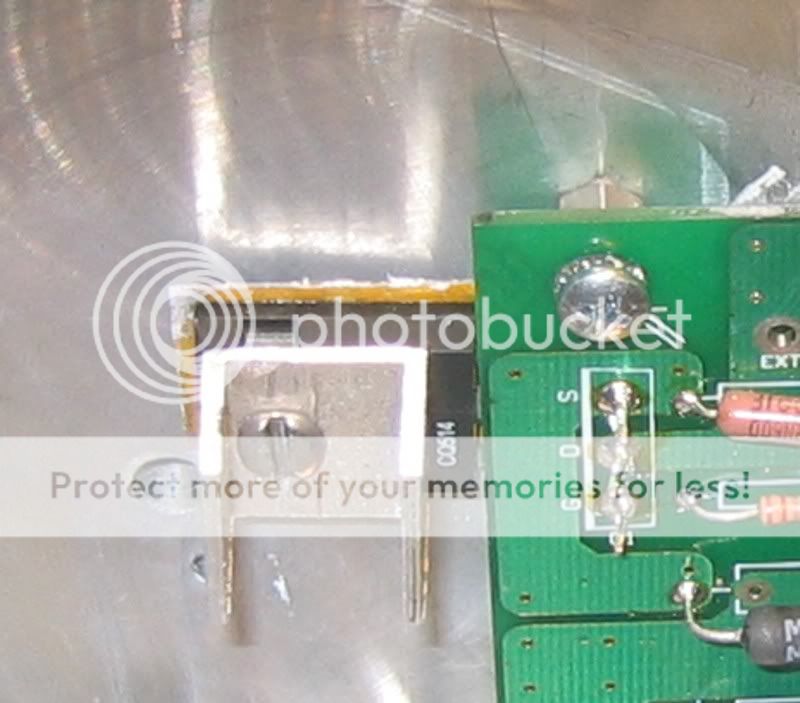
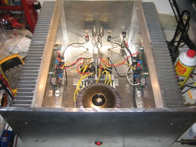
The only thing between the transistor and heatsink is a piece of kapton tape. It hangs out a tad past the edge of the transistor on all sides to make sure I didn't have any chance of metal to metal contact. perhaps that is what you are referring to. The heatsinks are polished where the transistors mate to them.
There are two large heatsinks per side and they are held together by the 1" X 1" X 1/8" aluminum angle top and bottom. There is one thing I didn't do. The kapton tape I have is sticky on one side. I applied it directly to the face of the transistor and then greased the side that mates to the heatsink. Tonight I will pull it apart and apply grease to both sides of the tape and see how much difference it makes.
I'm thinking I may just need to back down the bias a little. So, I have a couple of questions. Right now, if I understand this correctly, at 0.5V across the 0R15 source resistors and 14.75V rails, I am running at 6.5A bias. If I'm right then if I reduce the source resistors to 0.45V I should have 6A bias. Is this right? Is there any difference between lowering the voltage vs using say, 0R17 resistors and 0.5V drop? Could I go as low as 4V if I need to?
I would like it if I don't have to change all the 0R15 resistors. I went to the trouble to match all of them and my relative offset if right at 20mV.
After I posted last night, I let the amp run for another 1/2 hour or so. The heat sinks got up to 60C and the mounting screw measured 105C. You guys have got me worried that this is too hot.
Blessings, Terry
Kapton tape
Hi Terry,
I´m probably repeating myself but why don´t you just lower the bias with VR1 and VR3? This is much, much simpler than changing source resistors or the R in the C-R-C!
William
P.S. First I would use grease on both sides. What do the specs say for Rth junction to case for the fets you use?
I´m probably repeating myself but why don´t you just lower the bias with VR1 and VR3? This is much, much simpler than changing source resistors or the R in the C-R-C!
William
P.S. First I would use grease on both sides. What do the specs say for Rth junction to case for the fets you use?
Terry,
This Capton tape might do the trick but there's no listing of the thermal resistance in the PDF: http://www.argonmasking.com/pdf/64658-Argon 13-16.pdf
There are better materials around to fit your needs and I think you should hunt a bit more to find them.
Bergquist comes to mind, they have the Sil-Pad 2000 which has a thermal resistance of 0.2°C/W. If you can get your hands on very tiny Mica sheets you'll probably can do even better.
The Sil-Pad doesn't need grease, the mica does.
Meanwhile, get the bias down with V1, V3
/Hugo 🙂
Well, I don't think the fault is with the Kapton tape. Here's a list from Rod Elliot's site.
Material- Thermal- Electrical- Thermal Resistance -Other Properties
mica- Good- Excellent- ~ 0.75 - 1.0- Fragile
Kapton- Good- Excellent -~ 0.9 - 1.5 -Very robust
aluminium oxide- Excellent- Fair- ~ 0.4- Fragile - easily damaged
beryllia (beryllium oxide)- Excellent- Excellent- ~ 0.25- Toxic
Sil-Pads- Fair- Excellent- ~ 1.0 - 1.5- Convenient
I think I just need to lower the bias. 🙁
I will try to do it with V1 & V3. That is what I was asking about above when I said to drop the voltage across the source resistors.
In fairness, I haven't had enough time to compare them. The little bit I did compare, The krell seemed to have a little more presence in the midrange. I know that goes against almost every review I've seen but that's what I heard. The Krell is definately stronger.
I listened to the AX for about an hour last night and enjoyed every minute of it. However, I can say the same for the Krell. I will have a better opinion after I've had some time to evaluate it more.
I'm glad I built this Aleph. I've learned some things and it sounds good. Those are the two most important things to me right now. With hind sight, I probably should have used the specified devices instead of the OnSemi one's. Now I'll never know if it might sound better or worse with the IRFP's. Let me finish tweaking it and then I'll give a more enlightened opinion.
Blessings, Terry
Material- Thermal- Electrical- Thermal Resistance -Other Properties
mica- Good- Excellent- ~ 0.75 - 1.0- Fragile
Kapton- Good- Excellent -~ 0.9 - 1.5 -Very robust
aluminium oxide- Excellent- Fair- ~ 0.4- Fragile - easily damaged
beryllia (beryllium oxide)- Excellent- Excellent- ~ 0.25- Toxic
Sil-Pads- Fair- Excellent- ~ 1.0 - 1.5- Convenient
I think I just need to lower the bias. 🙁
I will try to do it with V1 & V3. That is what I was asking about above when I said to drop the voltage across the source resistors.
Terry
I have parts for two Aleph X lined up but with the KSA clone just finished I am wondering if it worthwhile building this amp ?
Does the amp sound better than the KSA clone you build
Jozua
Cape Town
South Africa
In fairness, I haven't had enough time to compare them. The little bit I did compare, The krell seemed to have a little more presence in the midrange. I know that goes against almost every review I've seen but that's what I heard. The Krell is definately stronger.
I listened to the AX for about an hour last night and enjoyed every minute of it. However, I can say the same for the Krell. I will have a better opinion after I've had some time to evaluate it more.
I'm glad I built this Aleph. I've learned some things and it sounds good. Those are the two most important things to me right now. With hind sight, I probably should have used the specified devices instead of the OnSemi one's. Now I'll never know if it might sound better or worse with the IRFP's. Let me finish tweaking it and then I'll give a more enlightened opinion.
Blessings, Terry
Hi Terry,
1-1.5 for Rth means 1 to 1.5°C per watt so in your case 50-75°C over the heatsink temperature. (wich almost fits)
I would try to put the grease on both sides first,
If that doesn´t work maybe you can try the Kapton foils from Fischer wich come with grease applied. The are specifies as having 0,07°C/W Rth wich is almost 20 times less.
I´ve used them on my Aleph5 and Aleph-X and measure less than 10°C difference between the IRFP240 case and the heatsink at 30 watts dissipation meaning an Rth lower than 0,33.
william
still4given said:
Hi Bob.
To be honest, I don't have clue what you are referring to.
The only thing between the transistor and heatsink is a piece of kapton tape. ...
Oops - early morning post - I mistook your angles on top for a plate of aluminum.
I stand by the part where I suggested moving your outputs closer to the center of each sink. I'll be that you find quite a temperature gradient across them
Hmm…you could be right about that Kapton, it’s probably just me who was suspicious about ‘sticky tape’, not really designed for that purpose.still4given said:Well, I don't think the fault is with the Kapton tape.
/Hugo 🙂
wuffwaff said:Hi Terry,
1-1.5 for Rth means 1 to 1.5°C per watt so in your case 50-75°C over the heatsink temperature. (wich almost fits)
I would try to put the grease on both sides first,
If that doesn´t work maybe you can try the Kapton foils from Fischer wich come with grease applied. The are specifies as having 0,07°C/W Rth wich is almost 20 times less.
I´ve used them on my Aleph5 and Aleph-X and measure less than 10°C difference between the IRFP240 case and the heatsink at 30 watts dissipation meaning an Rth lower than 0,33.
william
Hi William,
That's good to know about the case temp. If those figures are correct I guess I'm in the right range. I had 105C case temp and 60C heatsink 105-60=45C. I would guess that my Kapton tape is working then.
By the way, this tape is what I used. I will try grease on both sides and see what difference it makes. While I'm at it, I will try some mica insulators on a couple to see if there is any difference. I have plenty of mica insulators. I changed to Kapton because I thought it would be better since it's much thinner. I used it on my P101 per Rod Elliots recomendation.
BobEllis said:
Oops - early morning post - I mistook your angles on top for a plate of aluminum.
I stand by the part where I suggested moving your outputs closer to the center of each sink. I'll be that you find quite a temperature gradient across them
Hi Bob,
Yeah I thought about mounting them remote but wanted to try the original design first. The fact that they are mounted basically on the same fin of the heatsink can't be optimal but I hoped since they were so large it souldn't matter. Truth is, I measured the heatsink right between the two outputs and it only reads 61C, so I believe that the heat is geting dispursed. I try and check the temps across the heatsink and see how much heat is being lost. I need to buy another infrared heat guage rather than this probe type. It seems to work OK but it is slow heating up. Takes a long time to settle.
Netlist said:
Hmm…you could be right about that Kapton, it’s probably just me who was suspicious about ‘sticky tape’, not really designed for that purpose.
/Hugo 🙂
Hi Hugo,
I'm sorry if I came off wrong. I didn't mean to sound sarcastic. I can see how it could look that way.
I appreciate all of the advice I get here.
Blessings, Terry
I have never looked at it that way. So Terry, not the slightest problem here. 😉 Carry onstill4given said:I'm sorry if I came off wrong.

/Hugo
Hi Terry,
when I said "it fits" I didn´t mean that it was good. 1°K/W is way too high for your application.
The junction temperature will be quite a bit higher than the 105°C your measuring.
I would go for something else!
William
when I said "it fits" I didn´t mean that it was good. 1°K/W is way too high for your application.
The junction temperature will be quite a bit higher than the 105°C your measuring.
I would go for something else!
William
Hi Guys,
OK, last night I greased both sides and adjusted the bias down as far as I could. Weird thing is that the voltage will stay pretty steady until you get below .425V across the source resistors. Lower than that and it gets all squirly and the voltage is all over the place. At .425V it runs about 75C at the mounting screws. I still don't have any 10uf caps for the input so I can't really test the sound. With nothing connected to the inputs, I now have about 2mV relative offset. If I connect the preamp it goes to 3V offset. I htink I had better wait until I get those caps installed. If I can't get the temp down to a reasonable level I mahy add some more FET's.
Blessings, Terry
Hi,
so now you are at 5,7A instead of 6,6A.
Dissipation per device is now 14,75V x 2,83A = 41,8W instead of 49,2W (17% less)
If the screw now is 75V what do you have at the heatsink? You could calculate the new Rth with the grease applied to both sides.
(Tscrew-Tsink)/42 = Rth from case to heatsink.
William
Hi William,
OK, last night I got a chance to do a little more testing. I couldn't find any bipolar 10uF electros so I used polarized. Seems to work fine. Sounds good anyway and got rid of the DC offset when connected to the preamp.
Now as to the bias voltage, when I set this last I had .425V across the source resistors. Last night when I fired it up I read .485V. I checked the absolute offset and read 14.3V. Then it would swing to -9V, then back to 14V. After it all warmed up the absoute settled down to aroung 2V or less. It never really settles though. The relative offset started out around 60mV and dropped to 23mv after it warmed up. I've never had an amp with this much variance.
It runs more stable at about .450V so that is where I have it set right now. At this setting the heatsink stays around 54C and the mounting bolt for the output devices is at 90C. I think I will just leave it at that for a while and see how things go. It sounds very good right now. It is a lot less powerful than the Krell I built but it plays plenty loud with just a turn of the knob on the preamp.
I may think about adding more outputs if these fail. I would need to change the source resistors for that anyway.
Blessings, Terry
polarized electros on the inputs? 
 This is a spot for nice film caps - polypropyene or at least polyester.
A little breeze will make your offset go buggy - are you measuring with the top open?
The maximum power should only be a few db difference from your Krell. The AX has lower gain than many designs, so it will take more drive out of the preamp to make the same speaker volume. Is this what you mean by less power or is there a lower power sound to it?
This is a spot for nice film caps - polypropyene or at least polyester. A little breeze will make your offset go buggy - are you measuring with the top open?
The maximum power should only be a few db difference from your Krell. The AX has lower gain than many designs, so it will take more drive out of the preamp to make the same speaker volume. Is this what you mean by less power or is there a lower power sound to it?
- Home
- Amplifiers
- Pass Labs
- Aleph-X builder's thread