Member
Joined 2002
Re: Hi Grey,
Volt meter should read 15volts depending on the load. My mini a in the amp sets at 17.65vdc and in the PM around 10pm it is about 19.23VDC
weird eh.
carpenter said:Actually, I want the 15 volts +-. I just need to know: should my volt ohm meter read 15 volts +- while the amp is on?)
Volt meter should read 15volts depending on the load. My mini a in the amp sets at 17.65vdc and in the PM around 10pm it is about 19.23VDC
weird eh.
Hi
I have now all the parts to start building my Aleph X amps. The current caps I have are the Panasonics and the resistors are standard wire wound.
Would there any advantage in replacing the Panasonics with Black Gates and replacing the resistors with Mills resistors ? In a sense I want to make this an all out attempt to get the very best out of the amp. Alternatively should I just proceed with what I have ?
Any advice would be appreciated
Jozua
Hi Jozua,
The use of Panasonic FCs or Blackgates have been covered many times for the Aleph5. Was quite an extensive thread on it, "1,001 ways to better an Aleph".
I'm not sure how to say this but some prefer BGs and others prefer Panasonics with FKP??s or some polypropylene caps across them. Honestly, I think its an issue of personal preference.
Confusing isn't it? Not sure if this helped you. But if you're going on an "All out" approach, why not get BGs and some high quality polypropylenes.
Regards
methinks I gave some really ambigious answer😕
We don't need no stinkin' PCB's!!!
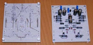
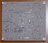
Finally finished building my Aleph-X boards. Wasn't able to find any spare pcb's leftover from a group buy, so I built them on perfboard. For a one-off build, I am hoping it will work just fine.
I am building them as monoblocks, aiming for +/-15V rails using PS boards from BrianGT's miniAleph PCB group buy, 94000uF-1.5mH-47000uF on each supply rail, which should give me about 8mV(peak-to-peak) ripple. Bias will be adjustable, but I am aiming for 0.55A total per channel. This should give about 50W into 8 or 4 ohms.
Here's a picture of my boards.
Attachments

Parts for Aleph X
Hi
This might have been covered before but has anybody ever build an NHB (No Holds Barred) Alelph X where the very best Caps and resistors and wires have been used ?
At what stage does one draw the line and does it become a waste of money to buy these very expensive components.
Jozua
Hi
This might have been covered before but has anybody ever build an NHB (No Holds Barred) Alelph X where the very best Caps and resistors and wires have been used ?
At what stage does one draw the line and does it become a waste of money to buy these very expensive components.
Jozua
Re: We don't need no stinkin' PCB's!!!
Metalman,
Nice job on the perfboard! I have a question (as always):
Are the trace "spikes" (you've got ten of them , I believe (see! I can count!)) sticking up through the top of the perfboard all for ground connections?
Idiotically yours,
Kofi
metalman said:Finally finished building my Aleph-X boards. Wasn't able to find any spare pcb's leftover from a group buy, so I built them on perfboard.
Here's a picture of my boards.
Metalman,
Nice job on the perfboard! I have a question (as always):
Are the trace "spikes" (you've got ten of them , I believe (see! I can count!)) sticking up through the top of the perfboard all for ground connections?
Idiotically yours,
Kofi
Kofi,
Actually there are 17 in total (there are 7 that are really hard to see in the photo) as follows:
1 each (3 total) for +V / -V / GND
1 each (2 total) for +IN / -IN
1 for each output transistor gate (4 total)
1 for each output transistor source (4 total)
1 for each output transistor drain (4 total)
I will be taking the output +/- off of the power resistors (It just happens to be a convenient method for the chassis layout that is currently under construction). I am using 4 IRFP044's for the output transistors.
Cheers, Terry
Hello
I have been slowly building my aleph X monos with Karis board. I have stuffed most of the resistors . I then realised that alot of people are matching resistors and using 0.1% . I am using 1% and where needed variable for tweaking will I still be able to manage dc offset ? or do I need to pay out for 0.1% etc ? I have matched my irf9610 down to 0.01 )
Does anyone have some info on how to measure dc offset and the other tweaks I willneed to do. Ie step by step for the layman... I will try it on my Aleph 5's before completing the X
rehards
dave
There are two types of offset with the Aleph-X to consider.Originally posted by dhole
Does anyone have some info on how to measure dc offset and the other tweaks I willneed to do. Ie step by step for the layman...
Absolute Offset: The voltage difference between an output terminal and ground.
Relative Offset: The voltage difference between the the positive and negative output terminals.
The absolute offset will affect your amplifier performance near it's maximum output, as the offset will cause the amplifier to start clipping at lower levels than can be achieved with proper adjustment. The good news is that the absolute offset can be set by adjusting the current in the CCS for the differential input transistors (the IRF9610's). Measuring it is easy using a multimeter, leave the amplifier on but with no input signal, connect the common probe to ground, the test probe to an output terminal, and read the voltage.
The relative offset is the one that can affect your speakers if it is too high in level. It is also easily measured. With the amp on and no input signal, measure the voltage difference between across the two output terminals. It occurs mostly due to mismatching between the Vgs of the input differential (this is why matching the IRF9610's is important), the resistance mismatch between the IRF9610 source resistors, the Vgs mismatch between the output gain transistors, and the mismatch between the resistance of the output transistors drain resistors. The bad news is that the relative offset is, in practical terms, not adjustable. That is why some of us are going to extremes with resistor matching or high precision resistors. There are two things that can be done to minimize/reduce the relative offset, which are included in the Aleph-X schematic. First is the ~5K resistors connecting the IRF9610 gates and drains. The second is the power resistors connecting the output terminals to ground. They are not mandatory for the circuit to operate, are are included solely to reduce the relative offset. Several people have built the Aleph-X using matched fet's and 1% resistors, and using the extra resistor additions produced relative offsets that were well within the acceptable range.
I should add that when you are measuring offsets, connect an 8 ohm power resistor between the output terminals to simulate the presence of a speaker.
Lastly, I am not one of the resident guru's, just a guy who has built and had to troubleshoot a few circuits. My info may not be perfectly accurate. If I have made any errors, usually the more knowledgeable folks around here will jump in with corrections.
I wouldn't say so, your stuff looks pretty darn good to my eye's. Also, your adventurous explorations of new circuits certainly exceeds my efforts. Why don't we simply agree that we have a friendly level of mutual respect for the work we have done.Originally posted by jh6you
Great, metalman!
Your diy quality is much better than mine.
Cheers, Terry
For relative offset, I would worry less about resistors and more about matching the active devices.
In some cases, I have managed to swap devices from one side to the other where the offset in the front end differential and the output stage tend to offset one another. I do not recommend this as a policy; do not assume that you can throw any old MOSFETs into the circuit and fiddle them into 0V offset. A well matched set of devices is still your best bet.
Grey
Hi Terry
Sure, we do mutual respect.
My wife has always commented to my internal wires: “Looks like a spider net.”
This time (F1), she has said: “No net . . . ? Oh . . . better. You now fairly advanced.”
I’m "really" impressed with the finish look of your breadboard.
All the best!
Regards
jH
Sure, we do mutual respect.
My wife has always commented to my internal wires: “Looks like a spider net.”
This time (F1), she has said: “No net . . . ? Oh . . . better. You now fairly advanced.”
I’m "really" impressed with the finish look of your breadboard.
All the best!
Regards
jH
Pass DIY Addict
Joined 2000
Paid Member
Question about Q3, Q4 and R11
Hi Everyone,
Quick change of topic for the Aleph-X. I'm starting to assemble several 100w (22v rails, 7-8A bias) monoblocks and have a question about using BC550 vs MPSA18 for Q3, Q4, Q8, and Q9.
From reading this and other threads, it seems that If you use BC550, you should use a value of 27k for R11 and R33, whereas if you use MPSA18 for Q3, Q4, Q8, and Q9, R11 and R33 should be 47K5. Is this correct? Or does the particular value not matter much since the trim pot is there?
Thanks!
Eric
Hi Eric,
this not only depends on the BC550 but also on the source resistors used. The lower these are the lower R11/33 plus pots must be to compensate. The value as such is not that critical cause you´ve got 100k´s to play with. I started with 27k to be shure I could get the bias low enough. Wenn I open the amps again I will measure what the value of pot plus 27k is for each amp.
William
Pass DIY Addict
Joined 2000
Paid Member
Thanks, William! Are you going to replace the pots with fixed value resistors then, or are you just measuring out of curiosity?
Eric
Eric
Pass DIY Addict
Joined 2000
Paid Member
Hi William,
When you get around to opening your case, could I trouble you to take a few extra voltage readings across some of the resistors or diodes in key parts of the circuit? It would serve as a helpful starting place for myself (since I'm essentially copying your design) and others who may eventually do the same...
Eric
- Home
- Amplifiers
- Pass Labs
- Aleph-X builder's thread