That last picture doesn't look very stock Aleph-X.
Why are you mounting transistors on auxillary boards when you
are only using 2 FETS per sid? Build it all on the board supplied,
it's a really nice PCB!
The gainclone isn't stock either... (way too much PSU capacitence)
Simplify... then you may be able to troubleshoot easier.
You ARE doing something wrong, becasue i have built the stock
Aleph-X and it DOES work.
good luck!
Hi moe29...
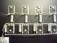
For aleph-X I'am using 4 mosfets per side , 8 per channel...so no place on PCB...( on picture is one channel )
GC, well I was just put it together to play some music...I did not bother to make it like stock GC...then I would have to make a really nice chassis for it...this is just to have something to play with...As Netlist say,to cool me down ( didn't find wine in frigerator ), and give AX another try...
Hi all
After checking all the resistor value, I still can get the absolute offset on my right channel down. It is still above +5V. I can't figure what has gone wrong.
Anyone having the same situation or experience?
Hock Hua
After checking all the resistor value, I still can get the absolute offset on my right channel down. It is still above +5V. I can't figure what has gone wrong.
Anyone having the same situation or experience?
Hock Hua
"After checking all the resistor value, I still can get the absolute
offset on my right channel down. It is still above +5V."
I think I remember having this same problem. I re-matched the
differential pair and mounted them together, back to back
(electrically isolated).
I thought I had matched close enough on the original pair, but
got a pair that had almost equal Vgs readings and it helped a lot.
What are the values of your diff pair current source?CH2 said:
After checking all the resistor value, I still can get the absolute offset on my right channel down.
You could compare them with these, assuming your rails are +/-15V.
/Hugo 🙂
Attachments

Here I'am again...one more question
since I have use 4 mosfets per side instead 2 and being use 0.5Ohm instead 0.22 and from wiki tread here is
R2 - 0.05V/(0.22/2)=0.45
R5 - 0.05V/0.22=0,23
AC current gain ( 1-(0,23/0,45))*100=49%
should I have in my case
R5 0.05/(0.5/2)=0.2
R2,3 0.05/(0.5/4)=0.4
(1-(0.2/0.4))*100=50%
so instead having 2 resistors of 0.22 in paralel I should have 4 resistors of 0.5 in place of R2,3 ???
Yoke
What you have now is the following:
Paralleled Output Resistors: 2 X 0.22 ohm
Output Source Resistors: 2 X 0.5 ohm
So you’re calculation should be:
0.05/(0.22/2) = 0.45 < -----Output R’s
0.05/(0.5/2) = 0.2 < -----Source R’s
1-(0.2/0.45))*100 = 56%
To simplify things a lot you could take the same value for the source resistors and the paralleled output resistors.
Then the rule is simple.
For each source resistor you mount a parallel resistor, that would be 4 X 0.5 ohm instead of 2 X 0.22 ohm your case.
All in all you are quite close to what it should be. 0.5/4 = 0.125 ohm and 0.22/2 = 0.11 ohm
When we recalculate everything with all same resistors we get this:
0.05/(0.5/4) = 0.4 < -----Output R’s
0.05/(0.5/2) = 0.2 < -----Source R’s
1-(0.2/0.4))*100 = 50%
So all you have to do then is measure twice 0.05V.
Hope this helps.
/Hugo 🙂
Netlist said:
What are the values of your diff pair current source?
You could compare them with these, assuming your rails are +/-15V.
/Hugo 🙂
Thanks Netlist, moe29 and all for the info. 🙂
I just did some check. My reading is very similar to Netlist's Diagram. My input voltage is +/- 14.7v.
The major difference is as below:
Between R24 & Q6a= 9.9v
between R48 & Q6a= 4.585v
between R26 & VR2= 14.76v
Q5 & Q7 was matched long ago. I remember the Vgs was the same. Maybe I was not consistent.
Cheers
Hock Hua
Thanks Netlist...
I will try to buy some more 0.5Ohm and then try option with 4x0.5 in paralel in place of R2,3...
I will try to buy some more 0.5Ohm and then try option with 4x0.5 in paralel in place of R2,3...
Hi All
I still can't solve the absolute offset Voltage problem.
I tried changing Q6a with another irf9610. The Offset voltage problem increases.
I tried changing r17 to 330 ohms. No help
I tried changing D1a to another diode. No help
I tried changing Q1 ,10 to Irfp044n. Even worse, the offset is at 12v. The irfp044n is not even turn on. No heat.
Any suggestion or info, on what I should try would greatly be appreciated.
Thanks
Hock Hua
Note:
I am using Grey Original circuit. J1 short to ground
maybe your error is in the power section? have you tested without output transistors?
you should get proper voltages and current in the diff-pair without the power transistors connected to + and -.
maybe one of the current source transistors for the output is burnt?
you should get proper voltages and current in the diff-pair without the power transistors connected to + and -.
maybe one of the current source transistors for the output is burnt?
dieringe said:maybe your error is in the power section? have you tested without output transistors?
you should get proper voltages and current in the diff-pair without the power transistors connected to + and -.
maybe one of the current source transistors for the output is burnt?
Thanks for the reply
Which is the current source transistor? Is it the Q2,11(IRFP240) on the bottom half of the board?
Thanks
CH2>
Use so called 'magic resistors' 🙂 Look here: http://web.vip.hr/pcb-design.vip/alephx.html
there are 2k2 resistors from each output node to the common source node of Diferential pair. Those resistors doses the magic task 😎
Piotr
Use so called 'magic resistors' 🙂 Look here: http://web.vip.hr/pcb-design.vip/alephx.html
there are 2k2 resistors from each output node to the common source node of Diferential pair. Those resistors doses the magic task 😎
Piotr
CH2 said:
Which is the current source transistor? Is it the Q2,11(IRFP240) on the bottom half of the board?
no I meant the small one, ZTX450 or the like
P.S. We can only guess. If you can't measure and/or find out which transistor is dead or which resistor has the wrong value or which trace on the pcb has a shortage you are very lucky that you have one working channel...
Hi, cooler specialists!
Maybe did not pay enough attention,
but there wasn't discussed a problem of - I think - general interest.
Many of ours own ready-made industrial coolers. Mines are 0.3 K/W pieces and will use two for each channel. Now the question: As everywhere you can find as first order rule matching the output MOSFETs (Q2,11) and only optionally the ACS ones (Q1,10), I thought this would be necessary thermally, too. The PCB's design would suggest, however, mounting the current sides together (e.g. Q1,2).
Which is the better solution? As I have already seen many beauties with the same cooler arrangement, the solution exists. And better to follow the proven solution.
Laci
Yes, love it. It can be so beautiful. The more you practice the better it gets.jam said:Hugo,
I see you like point to point wiring.......
I have tons of pictures from my AlephX's, too much to post, some with point to point arrangements.
I know you like pictures, I could send you some megabytes… 😀
Thanks Jam.
/Hugo 🙂
- Home
- Amplifiers
- Pass Labs
- Aleph-X builder's thread