Yes, but...Do they make LEDs that tiny?
Serious part - That's the intention. If you're talking about the PASSdiy chassis, then the holes go all the way through the front panel b/c they're specifically placed in the "sine wave". Just providing a pilot hole of a few cm deep could still allow error in placement by the user if they tilted the bit drilling through or picked too large a bit. Plus, two LEDs looks cool.Or do I need to simply drill the backside large enough to fit "normal" LED, like the Zenmod custom Iron Pre chassis LED openings?
Also, I scientifically calculated the exact diameter to give just the brightness I wanted.

Anyway... yep, for me the easiest thing to do is pick a drill bit just the tiniest smidge above the diameter of the LED body, but not the neck ridge, and go down about 3mm or 4mm, but not all the way through the front. It should friction fit, but if not... a little tape... some hot glue... or whatever works will hold them perfectly in place.
Last edited:

As far as how I deviated from the build guide I did have access to it but I kind of rushed through it and didn’t take the time to read it thoroughly the first time. I have since then read the aleph Jzm and f5m guides a few times. I would greatly appreciate that kit. I thank you for your generosity and I will certainly take my time to follow the build guide and do this correctly this timeI agree 100%. I (of course) have a bias, but I've added emphasis to one thing above that I am reasonably sure would help...
@yarozebob - As a pretty good rule, we're a lighthearted bunch that wants to help. Personally, I know if you take it slowly and follow instructions you'll have a working project. I am curious why you deviated so far from the build guide. You can PM me if you're more comfortable. Did you not find it? Should we make it more prominent on the sales page? Either way, when you're ready to resume, I'll send you over a new kit if you'd like. You cover postage. IMO, trying to repair what you've done would be an impressive commitment. However, if you'll promise to follow the guide... for your second try. I'll send you a new kit.

^ Shoot me your mailing address in a PM, and I'll get one packed up for you. I'm a bit swamped, so give me until end of next week before you nag me publicly if I don't get it out. I also tend to forget.
Have fun, go slowly.... it says it all (hopefully) in the guide.
Cheers!
Have fun, go slowly.... it says it all (hopefully) in the guide.
Cheers!
^ Do you mind sharing what iron you're currently using along with the solder? Do you have a pair of "side cut" snips or other cutters that do a nice job of cutting the leads close to the board?
Also... the fact that you tried to use solid core wiring... was (IMO) a large contributor to some of your initial issues. It's a challenge to work with in the best of circumstances nevertheless for the first time.
Technique definitely played a role, but IMO, you stacked the deck against yourself in a few ways. You'll be set up for success next go-around. I'm impressed you took on the project as your first. Kudos! Not every big swing is a homer.
@yarozebob chin up, no one gets born with those skills. In time you’ll learn to take the time needed, visualize wire routing, twisting, choosing guages etc
I remember when I started and I googled that silver wire was the best, and I thought I had solved the secret equation. Made such crappy tube circuits out of this planet. With silver wire and solder everywhere.
As the old wording say, it’s the journey, not the destination.
I remember when I started and I googled that silver wire was the best, and I thought I had solved the secret equation. Made such crappy tube circuits out of this planet. With silver wire and solder everywhere.
As the old wording say, it’s the journey, not the destination.
I used a cheap(probably Chinese made) soldering iron. Now I use this https://a.co/d/3ws7v46 and I now have a really nice pair of snips that @birdbox sent me^ Do you mind sharing what iron you're currently using along with the solder? Do you have a pair of "side cut" snips or other cutters that do a nice job of cutting the leads close to the board?
Also... the fact that you tried to use solid core wiring... was (IMO) a large contributor to some of your initial issues. It's a challenge to work with in the best of circumstances nevertheless for the first time.
Technique definitely played a role, but IMO, you stacked the deck against yourself in a few ways. You'll be set up for success next go-around. I'm impressed you took on the project as your first. Kudos! Not every big swing is a homer.
Last edited:
Thank you@yarozebob chin up, no one gets born with those skills. In time you’ll learn to take the time needed, visualize wire routing, twisting, choosing guages etc
I remember when I started and I googled that silver wire was the best, and I thought I had solved the secret equation. Made such crappy tube circuits out of this planet. With silver wire and solder everywhere.
As the old wording say, it’s the journey, not the destination.
Hello, just finishing my boards for AJzm and have a quality control question.
All good in general but my first solder pass at the large resistors was a bit messy (switching to larger tip on the iron did the trick!).
The clean up ended up with a possible solder bridge on top of the board betw R28 and R31.
Is this ok, or should i clean it up (see pic)?
as a novice, reading the circuit doesnt clarify for me.
Thanks in advance!
Attachments
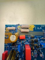
You are good to go. R28 is connected to R31 and R30 via a trace (and now some solder too).

Last edited:

That is exactly what I am inclined to do, just wanted to make sure I wasn't missing something obvious! Yes, leaving the small hole on front panel. I don't then need worry I will mar the faceplate either.On my homebrew stuff I drill the back of the panel to fit the LED body, and let the light shine through a tiny (or at least smallish) hole in front.
Hi folks,
Couple of questions as I progress towards finishing my Jzm build that I hope you can help with:
1. Board Placement - in the build guide - it shows the placement of the boards toward the bottom of the heatsink (which is actually the top in my photo). Why not move it up one row of threads so that the MOSFET's are closer to the center, seems like it may make accessing the boards for measurement (or tuning of potentiometers) easier. Just curious on this one. Photo 1 kind of demonstrates approximately where I am proposing to mount the boards.
2. Where can I get a pair of the wire management towers, I will need to do something to get my front panel LED's to stay put because my front panel only has two small holes for the "light" without larger holes on the back side of the front panel where I can set the LED's. I think my LED's are 5mm diameter similar size as the ones in the kit. Photo 2 shows the back panel with the tiny holes for the LED's.
3. I want to build my amp with XLR and SE inputs. The build guide, at Step 55 in the information bullet says to "remove the header cap from JP1" if using both SE and XLR inputs. Is the header cap what I have shown installed on JP1 in Photo 3, should this be removed? Or is the header cap the thing in Photo 4?
4. Also, the build guide in the same step and bullet says "When using the XLR inputs, you will need to use a shorting pin / plug between pins 1 and 3." Assuming XLR is a typo and it should say SE? The shorting pin link in the build guide shows something that inserts into the XLR, assuming that makes it unusable?
Sorry for the maybe obvious questions.
Thanks in advance for your help.
Jim.
Couple of questions
1. 1/3 of height from bottom
3 and 4. Jumper JP1 closed only if using SE (RCA) exclusively; if mounting XLR, it's necessary to put shorting bridge to XLR pinholes 1 & 3, when using RCA input; point is that for SE (RCA) input , negative diff. input of amp must be grounded
If you ask why is that needed, no short answer to that
Generally, you mount the devices ~1/3 up the sinks. In this case, you've got PLENTY of heatsink for the dissipation. Where you have them is perfectly fine.Hi folks,
Couple of questions as I progress towards finishing my Jzm build that I hope you can help with:
1. Board Placement - in the build guide - it shows the placement of the boards toward the bottom of the heatsink (which is actually the top in my photo). Why not move it up one row of threads so that the MOSFET's are closer to the center, seems like it may make accessing the boards for measurement (or tuning of potentiometers) easier. Just curious on this one. Photo 1 kind of demonstrates approximately where I am proposing to mount the boards.
You're covered there... from #596. 🙂2. Where can I get a pair of the wire management towers, I will need to do something to get my front panel LED's to stay put because my front panel only has two small holes for the "light" without larger holes on the back side of the front panel where I can set the LED's. I think my LED's are 5mm diameter similar size as the ones in the kit. Photo 2 shows the back panel with the tiny holes for the LED's.
Leave off the cap in #4.3. I want to build my amp with XLR and SE inputs. The build guide, at Step 55 in the information bullet says to "remove the header cap from JP1" if using both SE and XLR inputs. Is the header cap what I have shown installed on JP1 in Photo 3, should this be removed? Or is the header cap the thing in Photo 4?
Great catch! Fixed. 🙂 The plug / pin is only temporary while you're using RCA instead of XLR. You take it out... and the XLR is usable.4. Also, the build guide in the same step and bullet says "When using the XLR inputs, you will need to use a shorting pin / plug between pins 1 and 3." Assuming XLR is a typo and it should say SE? The shorting pin link in the build guide shows something that inserts into the XLR, assuming that makes it unusable?
Example Fancy Shorting Pin
I just bend some solid core wire.
Edited b/c I accidentally posted before putting in the shorting plug info.
Wow, thanks for the lightning quick responses @birdbox @Zen Mod @ItsAllInMyHead Much appreciated. These were the last questions I had prior to hopefully finishing up my build this weekend and firing her up!
Hey Gang, need some insight. I built a Aleph Jzm a few months ago and it seemed to be working fine. I few weeks ago it started humming on the right channel. Some times it would just give off a buzz and then stop, sometimes it would stay until turned off for a while. I also noticed it would stop sometimes after touching, tapping the chassis. I have attached a link to some pics and have been searching for a fault and last night noticed a spade connector that was browning/burning. Just now I turned it on and that wire Red from Trans to Supply board is getting real hot. Turned it off and here I am...
Looking to see of anyone has seen this problem and can give me a quick fix. I am thinking something on PS Board... oh it sounds quiet when not buzzing although I did notice sometimes "light/low vol" hum is present intermittently. It also hums when Preamp if turned off no change.
It does seem to start after 1-2hrs playing.
The Setup:
https://photos.app.goo.gl/FHRR79hn1GKGMrrK8
Internal Photos:
https://photos.app.goo.gl/B3ogzDUJDGLR3H9T7
Moving to my ACA and B1 for now...
TIA, for any thoughts...
T
- Home
- Amplifiers
- Pass Labs
- Aleph Jzm