If each diode has a 1v Vf, then 17V would be right, no?
However and also... I have no real idea about this - but output from the bridge is a weird waveform. Will your DMM read correctly on either AC or DC? What should it read? Peak voltage? RMS?
No. When rectifying ACV to DCV there’s a 40% gain in voltage, then approximately 0.7v voltage drop per diode, as a bridge always as two diodes in series, the drop will be around 1.4vdc.
18VAC x 1.4 = 25.2vdc
25.2 - 1.4 = 23.8vdc

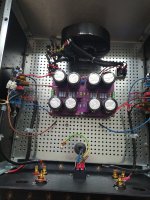
Have replaced the high reading 24VDC B /Rec with the other spare and they are both outputting the same 17VDC Have connected the board to the B/R and powered up for the first time through a DL Tester it glowed then faded quickly, no smoke /pops LED,s spark up, 24v DC across positive & ground both ends
I assume 24v across positive & ground in correct, as between positive & negative is much higher. I am using only RCA so i assume short RCA and install J1 cap or leave it off ?? Do I at some stage put the high reading B/rec back in as it has a snubber on it ?. Apologies for needing my hand held.
I assume 24v across positive & ground in correct, as between positive & negative is much higher. I am using only RCA so i assume short RCA and install J1 cap or leave it off ?? Do I at some stage put the high reading B/rec back in as it has a snubber on it ?. Apologies for needing my hand held.
Attachments
in generally
if you measure a power amp...please short the input RCA...this avoid oscillation of the power amp. (no signal in)
chris
if you measure a power amp...please short the input RCA...this avoid oscillation of the power amp. (no signal in)
chris
Last edited:
Brilliant!
Move to the build guide Step 60 and give it a glance. If you have questions, continue to post.
Move to the build guide Step 60 and give it a glance. If you have questions, continue to post.
@Alan D UK -
Pause to indulge a dodo, please. This is more @rhthatcher's wheelhouse, but...
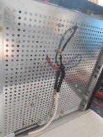
I don't see where your mains and your transformer primary connect to the PSU PCB. I see where the mains connects to the primary using the terminal block, but... I am clearly missing a critical connection. It's likely just a pair of wires I can't see in the photo, but for my own curiosity, would you describe how you wired AC mains through to the primary.
Edited to add - or did you intentionally bypass the soft start / safety cap?
Pause to indulge a dodo, please. This is more @rhthatcher's wheelhouse, but...
I don't see where your mains and your transformer primary connect to the PSU PCB. I see where the mains connects to the primary using the terminal block, but... I am clearly missing a critical connection. It's likely just a pair of wires I can't see in the photo, but for my own curiosity, would you describe how you wired AC mains through to the primary.
Edited to add - or did you intentionally bypass the soft start / safety cap?
Last edited:
Are connections on the botttom? How high is the board off of the bottom plate, and how are the wires connected? Is there any risk of a mains or primary wire touching the chassis?
^ The expert has arrived... I'll wait for @Alan D UK to confirm, but it looks like the wiring was originally 'per design' b/c I see the solder residue on the pads, and maybe posts from some male fast-ons, but it looks now like the primary is connected directly to mains => bypassing the soft start / safety cap.
Thanks for your concerns board is 30 mm high connections soldered, chassis is raised on nylon spacers cable needs tidy up and more clips, LED Cables will be re routed and zip tied later. please advise regarding soft start/safety cap is that TH1 have i made an error. Thanks
Attachments
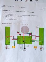
Are you wired up using the page of the PSU build doc with the header: "Amplifier Wiring Concept – 240V Mains – Option 2: One Pair of Primary Wires "?
I think I see:
Solder for mains wires fed from below
1 CL-60 for soft start
2 of 4 primary connections soldered from below
That wiring configuration leads to to think this is "240V Mains – Option 2: One Pair of Primary Wires" setup with wiring from below.
If this is the case, and you're seeing about 24V from ground to pos and neg and about 48V pos to neg you're good to go. That voltage will sag a couple of volts when loaded with amp boards.
Hi Randy
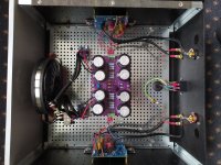
CL- 60 power supply BOM two required as per note for 240v mains TH1 & TH2 fitted TH3 BLANK. I had 49 volts across pos & neg, got me worried, 24VDC
ground to pos/neg. my earlier post regarding high output from one of the B/Rec 24VDC which i swopped out for two i purchased has the snubber on so at present both B/Rec have both snubbers omitted I assume 24VDC from ONE B/Rec is not an issue so will reinstate that one later. The Toriod was what you regarded as a good choice outside of the US TOROIDY TS 300VA 12 Ohm resister on Rs
Attachments
If you're getting 24V and 49V you're good. Snubbers are icing on the cake, and shouldn't have impact on the rail voltage reading when installed.
One thermistor is soft start, and the other thermistor is ground break. You should have 2 thermistors for your build, which you do. Good to go.
One thermistor is soft start, and the other thermistor is ground break. You should have 2 thermistors for your build, which you do. Good to go.
Today is a bit special, finally played music from phone to test Aleph Jzm WOW sounds amazing and that is before I play vinyl special thanks to rhthatcher who has been a great help, Birdbox also has been amazing sending me the Transformer throne and lots of other goodies & Zen Mod for the design & assisting me on this my journey and others 6L6 etc. Many Thanks
Attachments
- Home
- Amplifiers
- Pass Labs
- Aleph Jzm