In the short time I had today, I made all the changes suggested by Boky.
What has changed is that the "worse" channel is now the right one and the amp is quiet with open inputs and without me touching anything.
With the inputs shorted, both channels screech.
Could this be due to an Xformer? Or a broken bridge?
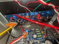
Here is a picture of how I attached the two xformers.

What has changed is that the "worse" channel is now the right one and the amp is quiet with open inputs and without me touching anything.
With the inputs shorted, both channels screech.
Could this be due to an Xformer? Or a broken bridge?
Here is a picture of how I attached the two xformers.
there are some specifics to your build, which you didn't even tried to present
anyhow........ cut one channel from PSU and try it solo
inform what's happening
we can't work with you if there is no proper correspondence - we asking, you doing your homework and replying, informing us of change
anyhow........ cut one channel from PSU and try it solo
inform what's happening
we can't work with you if there is no proper correspondence - we asking, you doing your homework and replying, informing us of change
Any preamp recommendations for the Aleph? Now I have a ba3 and I was thinking of changing it for the b1 buffer, would it be a good change? thank you and sorry for my English as a translator
Try only one power supply for both channelsIn the short time I had today, I made all the changes suggested by Boky.
What has changed is that the "worse" channel is now the right one and the amp is quiet with open inputs and without me touching anything.
With the inputs shorted, both channels screech.
Could this be due to an Xformer? Or a broken bridge?
Here is a picture of how I attached the two xformers.
View attachment 1237079
Have I overlooked something?
I have made the changes suggested by extreme_boky and reported back.
Tomorrow I will disconnect a channel from the power supply and try it solo and let you know what happens.
Many thanks for your help.
I have made the changes suggested by extreme_boky and reported back.
Tomorrow I will disconnect a channel from the power supply and try it solo and let you know what happens.
Many thanks for your help.
In the short time I had today, I made all the changes suggested by Boky.
What has changed is that the "worse" channel is now the right one and the amp is quiet with open inputs and without me touching anything.
With the inputs shorted, both channels screech.
Could this be due to an Xformer? Or a broken bridge?
Here is a picture of how I attached the two xformers.
View attachment 1237079
Can you confirm you wired the RCAs as per below??
The mechanical buzzing did come back and I found a culprit.
I had been testing this entire time with the diyAudio store speaker protection board. The protection board was powered by one of the transformer secondary leads and PSU ground. As soon as the relays kick in, the mechanical buzz increases significantly. I also tried to power the board by connecting to the pair of one of the transformer secondaries without touching the PSU ground. Same symptom. If I connect the speaker protection board to the +/- of one of the bridge rectifiers, it no longer buzzes.
I measured the current draw by the protection board - only 96 mA.
As a bonus, the noise coming from the speakers is also gone (when inputs are connected to a source).
I found some posts on the forum that half-wave rectification could cause toroids to complain. I wouldn't have expected 96 mA draw from the half-wave rectifier on the protection board to be the cause...
Has anyone else experienced this?
I found a (perhaps the) mistake I made... I had mixed the transformer primary wires. I was wiring it like this:
View attachment 1231519
After swapping 1 and 3, the buzz coming from the transformer is significantly reduced. The buzz coming out from the speaker also greatly reduced...
I happened upon freejazz00's posts while I was looking for ideas to try. I wonder if he had the same issue. The thermistors would definitely get hot.
My wiring definitely still needs to be redone and will try the hum breaker as well. I also have rectifier snubber boards from ThatcherDIYAudio I can try.
…But does it swing?Thank you all for the guidance. I've got it all wired up correctly and am enjoying the listening. Sounds lovely and is an amazing gift of this great community.
Success!

Great build.
Unfortunately, I didn't have time to work on the amplifier today.
But I still wanted to confirm boky's question.
The wiring is exactly as shown in the picture.
You should be able to see it here.


I'll report back as soon as I get round to implementing ZM's suggestions.
But I still wanted to confirm boky's question.
The wiring is exactly as shown in the picture.
You should be able to see it here.
I'll report back as soon as I get round to implementing ZM's suggestions.
Another Aleph J completed. Thank you Mr. Pass. Thanks to everyone for sharing their tips and experiences.
I am really glad I finally made use of those heatsinks I got from 2004.
To experiment with balanced input, I built a BOSOZ as well. The BOSOZ was something I had my eye on since the article was published but never got around to it (like the heatsinks...)

Took about a month to figure out why the transformer and speakers were buzzing. As soon as I connected the speaker protection board to DC instead of AC, it was fine. I probably made a mistake on the protection board somewhere... I haven't found anyone else reporting this issue on the forum. The turn-on delay and DC detection works fine though.

The PS board is from rhthatcher. It really helped to make the wiring less spaghetti.

I used a 2 x 55V transformer from Avel Lindberg and 7 x 8.2V (instead of 9.1V) zeners per rail for the BOSOZ.
I am really glad I finally made use of those heatsinks I got from 2004.
To experiment with balanced input, I built a BOSOZ as well. The BOSOZ was something I had my eye on since the article was published but never got around to it (like the heatsinks...)
Took about a month to figure out why the transformer and speakers were buzzing. As soon as I connected the speaker protection board to DC instead of AC, it was fine. I probably made a mistake on the protection board somewhere... I haven't found anyone else reporting this issue on the forum. The turn-on delay and DC detection works fine though.
The PS board is from rhthatcher. It really helped to make the wiring less spaghetti.
I used a 2 x 55V transformer from Avel Lindberg and 7 x 8.2V (instead of 9.1V) zeners per rail for the BOSOZ.

Salvaged from my Aleph 3 clone 😉:

I only learnt from the forum that Plitrons are no longer available when I started the J.
I only learnt from the forum that Plitrons are no longer available when I started the J.
Hi all, I'm hoping someone here can help troubleshoot an issue I'm having with my build. Before I go into the symptoms, I'd like to say that this is only an issue on the right channel amp board, the left channel and power supply are working perfectly, as validated by multimeter measurements and a listening test with the right channel removed.
What happened:
Parts:
Attached are pics of the front and back of the board, please let me know what troubleshooting steps you would recommend.
What happened:
During initial bias and offset adjustment, I was reading an extremely high DC offset on the right channel (about 20V). Adjusting R7 to reduce the offset resulted in the bias going very high, over 500mA. After several minutes of adjusting R7, R27, and R8 to try to get the offset and bias under control, the fuse eventually blew (3A slow blow). I removed the board to check for shorts, solder bridges, and visibly damaged components, and then finding none, I attempted to pre-set R7, R27, and R8 to their middle values. I replaced the fuse, triple checked all wire connections, and powered on the board but the fuse blew again almost immediately.
One of my suspicions is a potential short between the -V rail and ground because the -V rail LED on my power supply turns off quickly after the short, while the +V rail LED stays on. However, this suspicion is unconfirmed because with the board removed, a multimeter measurement between the -V and GND terminals on the board shows infinite resistance.
Parts:
I am using parts recommended by the rev D BOM (including a trim pot on R8) but D1 and all transistors came from the diyAudio Store "Aleph J MOSFET and JFET kit". I noticed that the BJTs in this kit were different than the BOM, but I believe they are compatable after looking at the datasheets.
Q1A, Q1B: LSJ74
Q2: S9015
Q3, Q4: S9014
Q5 - Q8: IRFP048
Attached are pics of the front and back of the board, please let me know what troubleshooting steps you would recommend.
Attachments

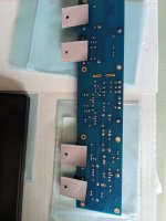
I can not tell from the photos if the Zener diode is soldered the correct way... it seems to me that it was not.
Something is causing a very high current draw... either a short as you mentioned, or one (or more) MOSFETs are shorted, or they get set to a completely "open" operation by the front-end CCS.
You have a good working channel, so something you could try is to unsolder both modules, use an ohmmeter and start comparing the resistance between various points. That will for sure show where the problem is.
Once you identify the problem, check each MOSFET for correct operation with a transistor tester... the chances are quite high that you'll need a new set of MOSFETs.
Last edited:
@Extreme_Boky Thank you for your response! I have attached a better picture of the zener, the orientation is the same on both left and right boards, and seems to align with the symbol on the PCB.
Do you mean simply to remove the amp boards from the rest of the system? I'm hesitant to desolder any components from the boards quite yet, especially on my working board, although desoldering may be the only step left to take. I have tried taking some resistance measurements around both boards, and many measurements refuse to settle to a single value, I think because of the presence of capacitors around the boards. I'll probably start by desoldering and testing the JFETs on the broken board when I'm ready.
I'm trying to think, if any single device was broken, which one would have caused the symptoms before the blown fuse?
Thanks again for your help, happy to hear any other recommendations you may have.
something you could try is to unsolder both modules, use an ohmmeter and start comparing the resistance between various points
Do you mean simply to remove the amp boards from the rest of the system? I'm hesitant to desolder any components from the boards quite yet, especially on my working board, although desoldering may be the only step left to take. I have tried taking some resistance measurements around both boards, and many measurements refuse to settle to a single value, I think because of the presence of capacitors around the boards. I'll probably start by desoldering and testing the JFETs on the broken board when I'm ready.
I'm trying to think, if any single device was broken, which one would have caused the symptoms before the blown fuse?
Thanks again for your help, happy to hear any other recommendations you may have.
Attachments
Last edited:
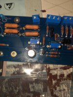
I am not sure why you have soldered the resistors in places that should only have the copper links...?
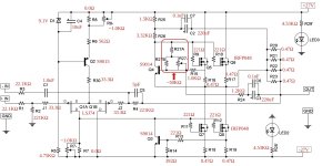
I have attached a few photos. The most important is the schematics with all the links removed, for clarity. There are some fault-finding tips there as well.
In your case, the fuse blows so, remove AMP PCBs and confirm that the PS PCB is good - confirm the unloaded DC rails voltage readings. There should be no voltage drop across those 4 x 5W / 0.47ohm resistors on each rail side (no current draw).
You should not remove any components from any PCB... Just disconnect the whole AMP PCBs and compare the DC resistances between the good and faulty sides.
There's the photo I attached of an assembled AMP PCB, so have a look and compare.
You could solder one end of the hook-up wires to the PCBs, and then use the lugs at the other end - crimp and solder... as per the attached photos. This will make the modules'' removal very simple and quick with no mess/fuss at all.
If the power supply is fine, and one AMP PCB works okay, then the other (faulty) AMP PCB could burn the fuse only if the MOSFETs are shorted, in which case you'll see the discolouration and smoke coming from R16 through R19.
Of course, you may have done something really silly... that my brain can not comprehend.... in which case:
- post the exact schematic
- post a lot of well-lit, in-focus photos of everything inside.
Good luck.
Thanks for the continued support!
I am using the rev D BOM from the diyAudio Store website, which gave me the choice to use jumpers or low-value resisitors in a few places. I opted to use resistors instead of jumpers for the added stability, just in case. I didn't want to rework the boards later on if I started encountering unwanted oscillations. Could this choice have caused my issues?
I can confirm that the power supply is still in good working order, although my supply voltages have always been slightly higher than the nominal spec: +-27V as opposed to +-24V on the schematic.
I will work on getting those photos for you, hard to find time in the middle of the week.
I am using the rev D BOM from the diyAudio Store website, which gave me the choice to use jumpers or low-value resisitors in a few places. I opted to use resistors instead of jumpers for the added stability, just in case. I didn't want to rework the boards later on if I started encountering unwanted oscillations. Could this choice have caused my issues?
In your case, the fuse blows so, remove AMP PCBs and confirm that the PS PCB is good - confirm the unloaded DC rails voltage readings.
I can confirm that the power supply is still in good working order, although my supply voltages have always been slightly higher than the nominal spec: +-27V as opposed to +-24V on the schematic.
I will work on getting those photos for you, hard to find time in the middle of the week.
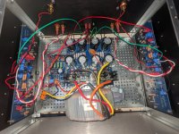
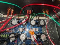
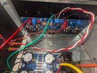
Here are some pics of my integrated build, hope it looks ok. I opted to use mostly screw-down terminals instead of spade terminals as you suggested. I find them easier to work with. Happy to provide more pics if it would help with the diagnosis. Do you see anything that would suggest an issue?
Attachments
@Extreme_Boky Attached is the detailed schematic of my build, as requested. The values were confirmed by inspecting the components and measuring them when possible.
I will keep investigating on my own, but I'm running out of ideas and would greatly appreciate further assistance.
I measured voltage across each of the 0.47 ohm resistors and each quickly settled to 0.0mVThere should be no voltage drop across those 4 x 5W / 0.47ohm resistors on each rail side (no current draw).
I will keep investigating on my own, but I'm running out of ideas and would greatly appreciate further assistance.
Attachments
- Home
- Amplifiers
- Pass Labs
- Aleph J illustrated build guide