The TD124 is a legendary table! I listened to a Thorens TD125 for years. It's packed away, never had the heart to sell it.FWIW, I run an Altec 414A with Altec 32C and 802D in an Altec 614 cabs driven by my Aleph J. Bass is excellent! Same result with Altec 416-B OB with LeCleach horns on top with Altec 288C (24 ohms). My brother runs a 4Pi speaker (15" JBL) with his AlephJ and the result is also the same. Have you tried CD or streaming as a source and get the same result?
My lowly TD124 and Garrard 301 have excellent bass using the amp/speaker combo I mentioned above and I fear sometimes that I will develop some rumbling issues due to the low end. I do not detect lack of bass with streaming via MacMini/Bifrost DAC as well.
Hope you find the culprit.
I think there is an issue with the 604 cabinets. They are a DIY modeled after the 842A cabinet, or Valencia. I need to check for leaks.
I can use the digital out on my macbook to feed the D/A converter in the DP400 and this produces the best bottom response.

Auricap = C1. I had a 1.0 Wima in there.auricap 1uF
which position?
post link to schm you're using
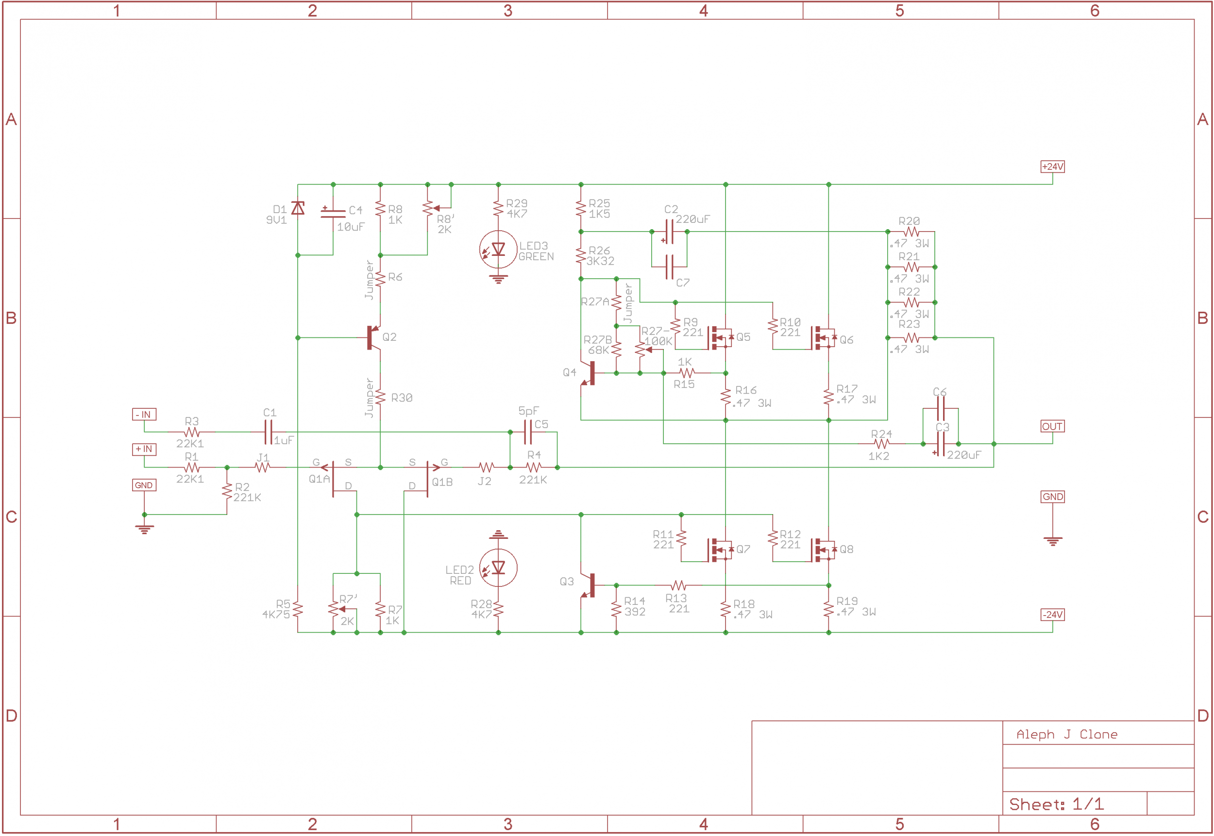
This schematic.
increase that to 4u7-10uF, or simply short itAuricap = C1. I had a 1.0 Wima in there.
there is your bass missing
F=1/(2*Pi*R*C)
R 22K
C 1uF
F 7.2Hz
means that you have phase twist well above 20Hz
^ Dang... I may have just had something sink in re: RC filters. I had no idea their importance in that location. I've never had a perceived lack of bass response in any of the Alephs, but I may try that mod in the Aleph J myself. Easy enough. Will try to learn re: "phase twist" too.
For my own goofy brain... looking at other Aleph schematics, are the relevant parts R1 and C5 (bypassed with C105) in the schematic attached? I ignored the MOSFET vs. JFET input stage etc,.
Would the F in this case be ~0.01 Hz?
R 68K1
C 220.1uF
H 0.001Hz
Am I on the right track?
Thank you!
Edited - What's a 0 after the decimal between friends....
Attachments
I asked if I had picked correct corresponding components in the schematic for the filter ... not if I should change the 220uF cap.
Sounds like I got it. 🙂
Thanks!
Sounds like I got it. 🙂
Thanks!
I too have never had a perceived lack of bass response in my AJ,
not until I swapped AJ with BA3 (complementary version) in the same system
not until I swapped AJ with BA3 (complementary version) in the same system
FWIW, the M2X to me mates better with Altec based speakers than an Aleph J. The difference is noticeable especially if you find , like I do, that a 2A3/300B amps makes your loudspeaker sing.The TD124 is a legendary table! I listened to a Thorens TD125 for years. It's packed away, never had the heart to sell it.
I think there is an issue with the 604 cabinets. They are a DIY modeled after the 842A cabinet, or Valencia. I need to check for leaks.
I can use the digital out on my macbook to feed the D/A converter in the DP400 and this produces the best bottom response.
For single drivers (like Fostex), to me, the Aleph J is the king!
Jumpered C1 and now the offset will not behave. Offset and bias do what you'd expect until I hit about 90V a/c on the mains. After that the offset jumps to 20V and bias drops to 0V. Any thoughts?increase that to 4u7-10uF, or simply short it
there is your bass missing
F=1/(2*Pi*R*C)
R 22K
C 1uF
F 7.2Hz
means that you have phase twist well above 20Hz
Couldn't find anything in this thread about phase twist. Can you explain or point me in the direction of some light reading?
keep C1, increase value to 4u7 (max 10uF)
phase - frequency dependent attenuating is in most cases resulting in changing phase of signal
C1 forms hi-pass filter with 22K
phase - frequency dependent attenuating is in most cases resulting in changing phase of signal
C1 forms hi-pass filter with 22K
I placed a 10uF in there but Q3 was already toast. The offset started climbing as soon the variac was powered on.
keep C1, increase value to 4u7 (max 10uF)
phase - frequency dependent attenuating is in most cases resulting in changing phase of signal
C1 forms hi-pass filter with 22K
Even if it doesn't solve your bass issue... I'd still highly recommend jumping In- to GND if it wasn't / isn't already done.
I placed a 10uF in there but Q3 was already toast. The offset started climbing as soon the variac was powered on.
there was some other problem, no doubt
I was routinely doing my iterations of Aleph J (Babelfishes known around) without cap in that position and even turn on/off thumps were mild, while no smidge of problem with DC Offset
-In did not have a jumper, it does now 🙂Even if it doesn't solve your bass issue... I'd still highly recommend jumping In- to GND if it wasn't / isn't already done.
No doubt there's another issue. The other channel dialed in with no problem. Offset fluctuates by 1mV but it has always done that. Q3 was fine, it just measured a little different that a new one but still within spec.there was some other problem, no doubt
I was routinely doing my iterations of Aleph J (Babelfishes known around) without cap in that position and even turn on/off thumps were mild, while no smidge of problem with DC Offset
I want to put a balance control for left right input, can I just use a pot- or is some sort of buffer needed ?
XLR in, or RCA?
The crude way would be to just place the pot across the left and right channels... this should work
The better way (if you do not need the full attention of R or L channels(, is to place the 2 resistors in series with the pot... this way you won't be shorting the hots to ground... Note: make sure that the ground point for the wiper is the GND eyelet on the AMP PCB !

The best way to do it is at the input of a buffer... Here, you could get creative... adjust the volume only for R and L independently... no need for two potentiometers 🙂 , i.e. no need for a separate balance pot...
.. or, adjust the negative feedback only, for L and for R, only as much to -> meet your needs... and not more than that..
Adjusting the volume for L and R channels independently would do the trick nicely... you could use a ladder-stepped attenuator switch... maybe only 6 steps??? -> they work nicely.
The crude way would be to just place the pot across the left and right channels... this should work
The better way (if you do not need the full attention of R or L channels(, is to place the 2 resistors in series with the pot... this way you won't be shorting the hots to ground... Note: make sure that the ground point for the wiper is the GND eyelet on the AMP PCB !
The best way to do it is at the input of a buffer... Here, you could get creative... adjust the volume only for R and L independently... no need for two potentiometers 🙂 , i.e. no need for a separate balance pot...
.. or, adjust the negative feedback only, for L and for R, only as much to -> meet your needs... and not more than that..
Adjusting the volume for L and R channels independently would do the trick nicely... you could use a ladder-stepped attenuator switch... maybe only 6 steps??? -> they work nicely.
Last edited:
ZM, can you clarify this for an amateur like me please. How does the cutoff frequency moving from 7.2Hz to 1.5Hz effect the bass response when both are in the inaudible range?increase that to 4u7-10uF, or simply short it
there is your bass missing
F=1/(2*Pi*R*C)
R 22K
C 1uF
F 7.2Hz
means that you have phase twist well above 20Hz
- Home
- Amplifiers
- Pass Labs
- Aleph J illustrated build guide