Nice!Hi, finally calming down with work stuff and no more excuses, need to get this thing moving! I think I am ready to test the power supply!
With an unloaded PSU, I like to start smaller. I use a 10W candle bulb. Note, use the actual power rating NOT the "equivalent to". Example, my "40W" bulbs are actually 29W. Either way, 75W is perfectly fine. Do you have a Variac (or equivalent) also?I have a dim bulb tester built (and a nice collection of old school incandescent bulbs, planning to use a 75W unless you suggest otherwise), so I have that to help.
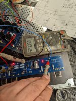
Nope. However, at least one more set of eyes is advised.Anything in these pictures give you concern, anything you can't see I should double check?
Fine. You can likely go down on the fuse rating for the live side, but nothing to be concerned with.3A slow-blow fuse on the Live, 10A non-slow-blow fuse on the Neutral (in the power plug/switch assembly)
Wise.The 'pants' on the CL-60's are jackets from silicone wire, rated for 200C, 6L6 told me how hot these things are.
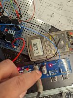
Looks correct. You'll know soon enough. 🙂 Looks like you have the ends of your secondaries paired off correctly, and you said you checked them for continuity. Also, the nice thing about those rectifiers is that one blade can be used as a visual reference for the placement of all the rest of the connections.On the first image, one pair (that I am touching) is going to one of the rectifiers, and hopefully I got the order correct on the rectifier itself.
Let us know how you progress!
Last edited:
I see. Might be a dead end then, but not terminating the shield at the board end is not how I would do it. It needs termination, otherwise it just acts like an antenna.hi Andy,
1.) The shield is connected at one end of the cable only to chassis ground(close to the input RCA). It is not connected to the GND on the amp board itself.
2.) Will try this.
Thank you!
Notice also the right channel output wires are crossed/intertwined with the very noisy wires from the bridge. Those two wires, in combination with the signal wire very close and the way the shield is connected, might be a major part of the reason for your noise levels.
So, in all simplicity what would the greatest amateur in the world (sissy moi) do?
- Disconnect the left chan from PSU. Listen again to the right chan, and measure
Vac.
- replace signal wire on the left chan with simple cat5/6 network cables, to remove sources of error (the shield). You can always replace later with shielded wires. Route this wire along the sink and back corner, keeping as far away from all other wiring as possible. Then short the input.
- Re-route the right channel output wire, keeping it close to the chassis floor, and as far from other wiring as possible.
Report findings, and possibly you will be able to do small adjustments to gradually make one chan quiet, before moving to the next.
Edit: I pull out, too many people helping. You can try these things in between

Regards,
Andy

ItsAllInMyHead - thank you! I might pillage an appliance lamp, something much smaller! Good to know I can go smaller.
If it works, I will have the worlds most expensive dual LED power supply!!!
If it works, I will have the worlds most expensive dual LED power supply!!!
@ andynor, IAIMH, Zen Mod, Vunce
Thank you for your help. Much appreciated!
I changed the PSU and re-dressed the wirings as shown in pic below. My brother docjrev who also built the AlephJ called me when I posted earlier about the hum and was very surprised about the ~4mVac hum. He sent me a pic of his amp with 0 hum. So we "thevenize" the freaking thing and it all turn out well.
Here it is! Hum free and full of muscle! Pic of the R-channel, 424 mVdc bias, zero humm, Yipppeeeee! 😀
Sounds great and offset and bias are steady on both channels after several hours! Even Sharif will like it (Rock the Casbah!)!
Last edited:

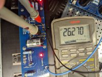
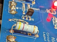
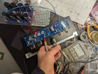
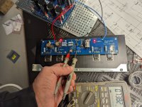
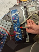
I spend 6h debugging my PCB but with no result. from the beginning, I got now bias current on mosfet and on input and output constant voltage ~26V
I've checked every resistor on PCB and desolder transistors and check. Is something missing me?
maybe someone got a similar issue?

I've checked every resistor on PCB and desolder transistors and check. Is something missing me?
maybe someone got a similar issue?
Attachments
-
 PXL_20230216_150653811.jpg552.5 KB · Views: 110
 -
 PXL_20230216_150710748.jpg518.6 KB · Views: 105
 -
 PXL_20230216_150716026.jpg529.9 KB · Views: 98
 -
 PXL_20230216_150729444.jpg523 KB · Views: 100
 -
 PXL_20230216_150744173.jpg595.9 KB · Views: 100
 -
 PXL_20230216_150749561.jpg527.8 KB · Views: 106
 -
 PXL_20230216_150845715.jpg553.1 KB · Views: 109
 -
 PXL_20230216_151059164.MP.jpg372.7 KB · Views: 109
 -
 PXL_20230216_151138946.jpg366 KB · Views: 118
 -
 PXL_20230216_151146117.jpg423.2 KB · Views: 118
 -
 PXL_20230216_151209596.MP.jpg506.7 KB · Views: 116
 -
 PXL_20230216_151226032.jpg447.4 KB · Views: 106
 -
 PXL_20230216_154802842.jpg605.3 KB · Views: 99
 -
 PXL_20230216_154821567.jpg511.5 KB · Views: 104
 -
 PXL_20230216_154841596.jpg552.9 KB · Views: 107
Last edited:
Inherent to the old power supply is my guess. The board based on my inspection looks like there's a ground loop based on the layout. I used the board to power my F4 and of course, no hum since there's no Vgain. I am planning to abused the board and cut the traces of the ground loops and see what it does. If it's no joy, I will surgically remove the filter caps and throw the board away or buy another case and build another F4 😀Great News!! 🥳
What was the causing the hum?
@rxr2 : Please see if you have any short between your rail and your inputs.
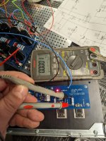
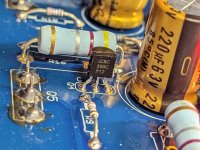
Also, your D1 voltage is bad; you should see about 9.1V there. You may have a damaged D1 or R5. Another possibility is a wrong and very high value R5 which is severely current starving D1. With power off, see if you can measure the resistance across R5.
Also, your D1 voltage is bad; you should see about 9.1V there. You may have a damaged D1 or R5. Another possibility is a wrong and very high value R5 which is severely current starving D1. With power off, see if you can measure the resistance across R5.
I've checked it's 4.8k ohm in documentation is 4.75k tomorrow I'll order new zener 9v1 and recheckedWith power off, see if you can measure the resistance across R5.
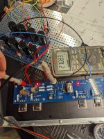
But even if zener diode failed it doesn't explain why on input + i got 26v it's seams like jfet failed
Transformer snubber installed each channel. Finally, done with this amp! Exceptionally nice sounding amp just like my M2X (snubbed as well )! 👍


I bought it long time ago from a group buy (2021). Search for member rthatcher as the board bears his name and if I recall correctly made the board and maybe he has some spares left from the run.
FYI, in case you do not have the Quasimodo test jig from Mr. Mark Johnson, to determine Cx,Cs, and Rs, user reported results on the thread below for common diy trafo samples. Enjoy!
Quasimodo Results Only
Quasimodo Results Only
Problem solve !@rxr2 : Please see if you have any short between your rail and your inputs.
Also, your D1 voltage is bad; you should see about 9.1V there. You may have a damaged D1 or R5. Another possibility is a wrong and very high value R5 which is severely current starving D1. With power off, see if you can measure the resistance across R5.
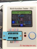
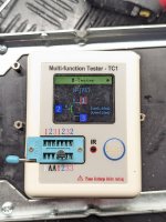
I don't know how my Chinese tester report Jfet is good but they aren't
I replace zener 9.1 and put new J175 OnSemi from a local shop ( on Monday ill be happy owner Oryginal 10pcs Toshiba 2sj74-bl)
So if someone got high voltage on in/out put problem is in Fets and they overload zener current source
Funny that I got them from DIYstore and I didn't make any mistake in soldering or any EMS during assembly.
But that's FETs they are very fragile...
Happy you've solved the problem.
BTW, have you tried measuring the jfet's Idss (say with a 9V battery)? I'm curious if that might show something since the photos you had of ~0.5mA @~320mV seem reasonable.
BTW, have you tried measuring the jfet's Idss (say with a 9V battery)? I'm curious if that might show something since the photos you had of ~0.5mA @~320mV seem reasonable.
- Home
- Amplifiers
- Pass Labs
- Aleph J illustrated build guide