uuuuuh, Tannoy biguns! 😍Hah!!
More confused with nursing a sick family. Damn viking immune system, nothing bites. The curse of being the unsick one
Yes, yes, these new additions hit hard and play smooth. But they need unshitty boxes!!
No Diana here: in Magna Grecia we have Artemis

Hi, finally calming down with work stuff and no more excuses, need to get this thing moving! I think I am ready to test the power supply!
I have a dim bulb tester built (and a nice collection of old school incandescent bulbs, planning to use a 75W unless you suggest otherwise), so I have that to help.
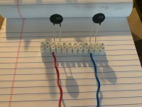
Anything in these pictures give you concern, anything you can't see I should double check? I purposely left the wires long and after I am happy with the layout and everything works, I will trim and re-terminate.
3A slow-blow fuse on the Live, 10A non-slow-blow fuse on the Neutral (in the power plug/switch assembly)
The 'pants' on the CL-60's are jackets from silicone wire, rated for 200C, 6L6 told me how hot these things are.
On the first image, one pair (that I am touching) is going to one of the rectifiers, and hopefully I got the order correct on the rectifier itself. The diagram on page 1 is confusing, but the one on page 6 makes sense and matches the Blogspot build guide many including myself are using. Using this part 512-GBPC3502:
https://www.mouser.com/datasheet/2/308/1/GBPC3510_D-1810327.pdf
On the second image, I am showing the two wires I am touching (with 3 and 4 dots) are from one 'pair' going into the transformer, I checked continuity, not just visual, but the continuity 'made sense' with how the two pairs of wires come out of the transformer.
The wires coming off the power supply board are for the LEDs - I drilled out the front panel and will hot glue them in. Nice dim blue ones with a wide dispersion angle so they should glow and not shine.
Thanks!


I have a dim bulb tester built (and a nice collection of old school incandescent bulbs, planning to use a 75W unless you suggest otherwise), so I have that to help.
Anything in these pictures give you concern, anything you can't see I should double check? I purposely left the wires long and after I am happy with the layout and everything works, I will trim and re-terminate.
3A slow-blow fuse on the Live, 10A non-slow-blow fuse on the Neutral (in the power plug/switch assembly)
The 'pants' on the CL-60's are jackets from silicone wire, rated for 200C, 6L6 told me how hot these things are.
On the first image, one pair (that I am touching) is going to one of the rectifiers, and hopefully I got the order correct on the rectifier itself. The diagram on page 1 is confusing, but the one on page 6 makes sense and matches the Blogspot build guide many including myself are using. Using this part 512-GBPC3502:
https://www.mouser.com/datasheet/2/308/1/GBPC3510_D-1810327.pdf
On the second image, I am showing the two wires I am touching (with 3 and 4 dots) are from one 'pair' going into the transformer, I checked continuity, not just visual, but the continuity 'made sense' with how the two pairs of wires come out of the transformer.
The wires coming off the power supply board are for the LEDs - I drilled out the front panel and will hot glue them in. Nice dim blue ones with a wide dispersion angle so they should glow and not shine.
Thanks!
Can I have the floor? 🙂
I have been troubleshooting my AlephJ in 4u chassis for hum on both channels (I am using 94dB speakers so its a little loud). All resistors checked, bias and offset are 425mVdc and +- 9 Vdc. In(-) jumpered to GND. R8 is a pot and not just a 1k resistor.
I have done the following:
1.) Ensure that the RCA's are isolated from the chassis.
2.) Rotate trafo (AS5218) 90 and 180 degrees on the X plane, 90 and 135 degrees on the Y plane (I think).
3.) Created a ground bridge (white wires between the two boards on pic 2).
4.) Disconnected GND from PSU via CL-60 near IEC out on pic 2, then use CL-80 for each channel connected to chassis ground with each ends to PCB GND near "Out" on the board.
5.) Shorted inputs, no inputs, L disconnected, R disconnected.
6.) Moved bridges away from trafo.
..... no change in hum magnitude.
However, if I disconnect left rectifier bridge from the trafo, the amp is quiet. Re-connecting left bridge and disconnecting right bridge, hum is present.
Any suggestions?
Thank you!
you have just one power GND for both channels, so best having NTC from PSU pcb to chassis
put that back, to avoid multiple GND loops
and then
what's hum level when both RCAs are shorted?
put that back, to avoid multiple GND loops
and then
what's hum level when both RCAs are shorted?
You must mean +-9mVdcbias and offset are 425mVdc and +- 9 Vdc
I don't think it's a good idea to disconnect one bridge rectifier and run the amp on a single power rail?
ZM, it's there. First pic, below the Neutral wire (White). Hum (input shorted) =7.5 mVac; un-shorted with no input = 2.6mVac.you have just one power GND for both channels, so best having NTC from PSU pcb to chassis
put that back, to avoid multiple GND loops
and then
what's hum level when both RCAs are shorted?
@KevinHeem - yes, +- 9mVdc and lower.
@Vunce - understood!
Hmmm...
Maybe I'm not familiar with the specific psu board your using. But, it looks like both channels have only a green LED lit, not the red also. Wouldn't that mean only one supply rail is feeding both amp boards?
Maybe I'm not familiar with the specific psu board your using. But, it looks like both channels have only a green LED lit, not the red also. Wouldn't that mean only one supply rail is feeding both amp boards?

OK
next test
connect main power GND pad of one channel with fat wire to same of other channel
inform what you got
btw. I've sen some Boyz did solve their hum problems, inserting 10-15R resistor between input GND pad and rest of the circuit
practically cutting the trace and inserting said (small ) resistor
that's so called ground breaking resistor
I'm sure you'll find it if you go back in thread, patiently
I did that with same results, hum about 4 mVac input open. On pic 2, you can see two white wires soldered to each PCB GND. I tried connecting them together to no avail. I also tried each with NTC on each end (CL80, ~65 ohms) then to chassis GND (using the device pictured) , with the PSU---> NTC---chassis GND connected and disconnected.connect main power GND pad of one channel with fat wire to same of other channel
inform what you got
Attachments
4-ish mV is way too loud. Something is amiss. The circuit is sensitive to noise.I did that with same results, hum about 4 mVac input open. On pic 2, you can see two white wires soldered to each PCB GND. I tried connecting them together to no avail. I also tried each with NTC on each end (CL80, ~65 ohms) then to chassis GND (using the device pictured) , with the PSU---> NTC---chassis GND connected and disconnected.
Apart from twisting all power wires even tighter, I would consider the following:
1: Am i seeing this correct? Is your signal return shield connected straight to the chassis? If soc you are feeding the return with all kinds of drek noise from the chassis. I would solder that wire straight to signal return pad of input jack, minimizing impedance for the return bringing the noise upstream.
2: Move signal wires to corners of the chassis instead of straight above the noisy psu.
And yes, the gnd lift/hum breaker works. But I’d be surprised if that is the only issue seeing as you have 4mVac
@amandarae
If I read properly, it's interesting (to me) that your noise increased with the inputs shorted.
"Hum (input shorted) =7.5 mVac; un-shorted with no input = 2.6mVac."
So I was looking for things that might contribute to that. Also, your noise (as Andy noted) is a few orders of magnitude higher than a factory unit (100uV spec).
What I'm looking for is more information re: how you've wired the input.
In- should be shorted to GND since you're using only SE inputs. As Andy mentioned, you can choose your own ground scheme... but it looks like you have your wire's shield connected from chassis to audio GND, and I do not see the In- to GND jumper. I'd disconnect the shield at both ends and ensure the jumper from in- to GND is in place as a test.
If you've included the connection from In- to GND (some folks do that on the back of the board or directly at the input jack or other fun places that might not be visible in the picture) then you can ignore that part. Either way, but I'd still try disconnecting the shield wire. Then, I'd try Andy's suggestion in #1 if you choose to resolder it.
There may be much better ways to approach it, but given Andy's and ZM's advice, that's where I'd head next.
Hope you get it sorted. Hum busting is a pain!
Totally unrelated... but ummmmm.... what's up with the top picture in #9145? That's a super, duper neato amp! Took me a second.
If I read properly, it's interesting (to me) that your noise increased with the inputs shorted.
"Hum (input shorted) =7.5 mVac; un-shorted with no input = 2.6mVac."
So I was looking for things that might contribute to that. Also, your noise (as Andy noted) is a few orders of magnitude higher than a factory unit (100uV spec).
What I'm looking for is more information re: how you've wired the input.
In- should be shorted to GND since you're using only SE inputs. As Andy mentioned, you can choose your own ground scheme... but it looks like you have your wire's shield connected from chassis to audio GND, and I do not see the In- to GND jumper. I'd disconnect the shield at both ends and ensure the jumper from in- to GND is in place as a test.
If you've included the connection from In- to GND (some folks do that on the back of the board or directly at the input jack or other fun places that might not be visible in the picture) then you can ignore that part. Either way, but I'd still try disconnecting the shield wire. Then, I'd try Andy's suggestion in #1 if you choose to resolder it.
There may be much better ways to approach it, but given Andy's and ZM's advice, that's where I'd head next.
Hope you get it sorted. Hum busting is a pain!
Totally unrelated... but ummmmm.... what's up with the top picture in #9145? That's a super, duper neato amp!
Took me a second.
Last edited:
hi Andy,4-ish mV is way too loud. Something is amiss. The circuit is sensitive to noise.
Apart from twisting all power wires even tighter, I would consider the following:
1: Am i seeing this correct? Is your signal return shield connected straight to the chassis? If soc you are feeding the return with all kinds of drek noise from the chassis. I would solder that wire straight to signal return pad of input jack, minimizing impedance for the return bringing the noise upstream.
2: Move signal wires to corners of the chassis instead of straight above the noisy psu.
And yes, the gnd lift/hum breaker works. But I’d be surprised if that is the only issue seeing as you have 4mVac
1.) The shield is connected at one end of the cable only to chassis ground(close to the input RCA). It is not connected to the GND on the amp board itself.
2.) Will try this.
Thank you!
@IAIMH
Thanks you!
1.) See explanation for shield above when I answered Andy's observation. In- is jumpered to GND at the board, I will post a clear picture later on.In- should be shorted to GND since you're using only SE inputs. As Andy mentioned, you can choose your own ground scheme... but it looks like you have your wire's shield connected from chassis to audio GND and I do not see the In- to GND jumper. I'd disconnect the shield at both ends and ensure the jumper from in- to GND is in place as a test.
2.) ill post pic soon when light is good.What I'm looking for is more information re: how you've wired the input.
Thanks you!
- Home
- Amplifiers
- Pass Labs
- Aleph J illustrated build guide