
Same here Kevin! Same 5U chassis with UPSB from the store. Virtually identical to my M2X build except the blue-colored led lights (green on the M2X) on the anti-vandal switch and the M2X is silent on all 7 cards I tried except for the Cedarburg (8th) IPS in my experienced (but much much softer thump than the AJ).
I think I have to put the thump to the "nature of the beast" category. We'll see if I can tolerate it in the long run.
I think I have to put the thump to the "nature of the beast" category. We'll see if I can tolerate it in the long run.

Hi Andy,The J is thumpy, just they way the circuit works. Turn on delay circuit will cure that, but I would’t worry too much about it.
The thump is during power Off. Quiet when turning On.
There's a 3' piece of speaker cable connected to the load. Actual resistance at the amp end of that cable is 8.1ohmWhat was the load? 8 ohms? Did you connect the load at the end of the speaker cables, or at the binding posts?
Maybe some one bought only the boards on the store and is using his own parts.... so here a little story.
I like to chase the second harmonic negative and positive phase, in Spice, as well as in reality.
So today I took my Aleph J from the basement. The board was populated with the cap and resistor values from Nelsons circuit floating around.
I like to chase the second harmonic negative and positive phase, in Spice, as well as in reality.
So today I took my Aleph J from the basement. The board was populated with the cap and resistor values from Nelsons circuit floating around.
Attachments

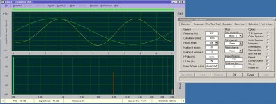
The I used REW first and my Focusrite to get an Impression of THD Pattern. All was fine with one side, 0.034% at 1W/8Ohm and H2 about 20dB higher H3.
The other channel showed a high distortion of 0.26%. So what? My suspicion was some oscillation and indeed touch with two fingers the both ends of the R27 made the distortion go lower.
I placed a 100pF cap parallel to the R27 and distortion went to the same 0.034%. Fine!
Forgot to mention that I had to go down with the R27 68k to 15k to get the 0.4V over one 0R47 source resistor. I will come back to this point later.
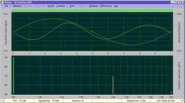
Now it was time for Diana to see the residual.
I hoped to have the neg phase H2 with the R24 Aleph resistor 1k2, this was not the case nice pos phase H2.
The other channel showed a high distortion of 0.26%. So what? My suspicion was some oscillation and indeed touch with two fingers the both ends of the R27 made the distortion go lower.
I placed a 100pF cap parallel to the R27 and distortion went to the same 0.034%. Fine!
Forgot to mention that I had to go down with the R27 68k to 15k to get the 0.4V over one 0R47 source resistor. I will come back to this point later.
Now it was time for Diana to see the residual.
I hoped to have the neg phase H2 with the R24 Aleph resistor 1k2, this was not the case nice pos phase H2.
Attachments
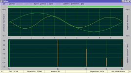
So what? I had in Spice neg phase H2 with 2k for the R24, but not in real, still pos phase. Spice predicted the change from 68k to the 15k for R27, but for the phase Spice was not correct.
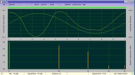
So I went down with the value a mix of 510R and a 500R pot was soldered. Astonishing how sensitiv the 10 turns pot trimmed the residual.
Nearly a matter of Ohms....!
coming nearer with 640R
So I went down with the value a mix of 510R and a 500R pot was soldered. Astonishing how sensitiv the 10 turns pot trimmed the residual.
Nearly a matter of Ohms....!
coming nearer with 640R
Attachments
So some thoughts.....
I think the 1k2 value for the R24 is only adequate for a certain transconductance of the lower IRFs. This could also explain the Nelson gives us the value of 4.3V at the 1k R7 for a bias of 1.6A around.
My IRFs seem to have a lower transconductance, I needed around 5V to get the 1.6A.
Is it possible that this is also the reason for the need of my lower Aleph resistor R24?
So I can only recommend, the you have a curve tracer or can measure your IRFs in another way for the Vgs at 0.8A you might be more on the save side.
Mixing the IRFs without matching will it make possible very difficult to chase the neg phase.
Looking again at my IRFP240 curves from the curve trace I think the 5V I mentioned are funny .... I will measure again, tomorrow.
Now its time for Jazz concert in town!
:--))
Has anybody a professional idea why I must take 15k for the bias resistor R27 instead of the 68k, what is the dependency?
Now its time for Jazz concert in town!
:--))
Has anybody a professional idea why I must take 15k for the bias resistor R27 instead of the 68k, what is the dependency?
presume is that there is one Vbe across R16, corrected with pull-up action of R27
so, some say and count that Vbe is 600mV, some say and count that Vbe is 650mV, some say and count that Vbe is 700mV
in first case, that's 1A276
second case 1A383
third case 1A49
far from professional idea ........ but let's say that everything counts in, variation of mosfet Ugs, beta of small TO92, tolerance of 0R47, value of (sum of) R25 and R26
who cares, as long you're able to set it
I remember that wicked noise you referred to... It happened to me once when I did not have XLRs connected to Aleph J. With XLRs (and source impedance 🙂) connected - there should not be any wicked high-frequency noise audible when powering AJ off.I was worried about my speakers…like I said it’s a wicked noise (with higher frequency components) not just a little thump.
Edit:
I’m using something other than the store PS, that could have something to do with it.
The turn-off thump is a trade mark... the severity is directly proportional to Iq; the lower the Iq the softer the thump.
”The turn-off thump is a trade mark”
It seems like i have to be the evil truth sayer dude some dude will hate tonight… 🙃
Well? Here it is: If that Aleph J ”thump” is to much for the main ”speakers” in your collection it might be time to give them to your mother in law and build a couple of actual real speakers for your self.
🎷 🎸
🎸
It seems like i have to be the evil truth sayer dude some dude will hate tonight… 🙃
Well? Here it is: If that Aleph J ”thump” is to much for the main ”speakers” in your collection it might be time to give them to your mother in law and build a couple of actual real speakers for your self.
🎷
🎸- Home
- Amplifiers
- Pass Labs
- Aleph J illustrated build guide