Thank you, learned something again.
Am I correct in assuming that:
When f1 is a frequency and T1= 360°means a period of a sine H1 as fundamental,
And H2 is its second harmonics
Then H2 phase is from -90° to +90° or from 0° to 180° always related to H1
I know that:
• Negative phase H2 in REW is shown as 90°
• With this LTspice tool and DIANA as you showed it
But how does it correlate with values 'Phase' and 'Normalized phase' for H2 from Error_log in LTspice?
But how does it correlate with values 'Phase' and 'Normalized phase' for H2 from Error_log in LTspice?
I do not know it, but some people here can it do, hope they see this....
I do not know it, but some people here can it do, hope they see this....
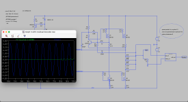
Here's another H2 phase dialysis with residual decoder.
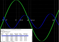
Pic is magnified part from my sim with residual decoder and FFT. H1 is fundamental - green, H2 is 2nd harmonics - blue.
Residual decoder: fi(H2) = fi(H1) - 108°
LTspice Error log: fi(H2) = fi(H1) - 147°
There is some discrepancy between the LTspice error log and the residual decoder, but the trend is OK.
Attachments
Hi all-
Soon after soldering the R5 resistors to the amp boards, in my case a pair of 1/4 watt RN60Ds as specified by BOM Rev. D, I noticed the other resistor specified for that position is a 1/2 watt Vishay. I’ve seen a couple of posts reporting that more than 250mW was seen there. I’m wondering if anyone else has found themself in this situation and felt compelled to desolder and replace that resistor with the higher rated one. I’d just like to hear from the forum in general what the consensus is and what is recommended to do here, before I execute a tricky desoldering operation I’d really rather avoid.
Soon after soldering the R5 resistors to the amp boards, in my case a pair of 1/4 watt RN60Ds as specified by BOM Rev. D, I noticed the other resistor specified for that position is a 1/2 watt Vishay. I’ve seen a couple of posts reporting that more than 250mW was seen there. I’m wondering if anyone else has found themself in this situation and felt compelled to desolder and replace that resistor with the higher rated one. I’d just like to hear from the forum in general what the consensus is and what is recommended to do here, before I execute a tricky desoldering operation I’d really rather avoid.
Just leave it.
The non-mil speced version of RN60 is the CMF60, which is higher rated than the CMF55 alternate resistors.
The RN60 rating is only lower because it is heavily derated (for mil-spec).
The non-mil speced version of RN60 is the CMF60, which is higher rated than the CMF55 alternate resistors.
The RN60 rating is only lower because it is heavily derated (for mil-spec).
As our esteemed Mr. Hui says, the RN60 is a 1W resistor that says 1/4W on the datasheet, because of the derating required to qualify for the milspec.
So yep, don’t worry about it.
So yep, don’t worry about it.

Don't be so pessimistic!I was wrong. It is Dialysis after all.
😉
:--))
(Mouser# 667-ERX-3SJR47) Panasonic Metal Film Resistors - Through Hole 0.47ohm 3W 5% for R16-23 are not produced anymore.
Those of Vishay are so expensive.
Are there alternatives?
https://www.mouser.kr/ProductDetail/KOA-Speer/MOSX3CT521RR47J?qs=m/CZjK2YaEJsJia8p8nbVQ==
This is metal-oxide not metal-film. Is it OK?
Those of Vishay are so expensive.
Are there alternatives?
https://www.mouser.kr/ProductDetail/KOA-Speer/MOSX3CT521RR47J?qs=m/CZjK2YaEJsJia8p8nbVQ==
This is metal-oxide not metal-film. Is it OK?
Perhaps others will chime in, but I personally wouldn't worry about using the KOA-Speer.
I thought Mouser still has some of the Panasonic resistors available. Perhaps not anymore. 🙁
Anyway, if you can order from other sources, the Panasonics are still available (at least for now) should you wish to persue them.
For example they can be found at Digikey and Newark (and probably other retailers):
https://www.digikey.ca/en/products/detail/panasonic-electronic-components/ERX-3SJR47/36497
https://canada.newark.com/panasonic/erx-3sjr47/resistor-0-47ohm-3w-5-axial/dp/52W8322?ost=erx-3sjr47
I ordered Panasonic ERX-3SJR47 resistors from Chip One Stop.
Thank you.
Thank you.
I have the boards since 2022 and finished the amps almost two-weeks ago. Ended up at 450 mV dc bias and almost 1mV dc offset. Played with bias and as I approached 500 mV dc, detail increases a bit I think,but settled back to 450 mV. Very nice sounding amp!


Oh, one question. If R6 and R30 are jumpered, and in the LTP bias position is a 2K pot, where to measure to ensure the pot is set to 1K (as I forgot setting this in the procedure)? What should be the voltage at the top (emitter ) of Q2 or below R8 with respect to ground?
Thanks!
Thanks!
put 1KHz sine, 1W at output, through dummy load (8R)
measure voltage AC across source resistor in lower rail, write down
measure voltage across AC resistor in upper rail, write down
inform here
goal is to find what Aleph CCS AC gain you have actually
meaning - when said is approx 50%, that means that upper half of amp OS ( exactly Aleph CCS) is having same voltage/current contribution as lower part of amp, practically amp acting as regular PP amp
if said gain is lesser than 50%, amp is leaning more to pure SE mode of operation, thus being more dependable of load value and behavior
now, having 604, efficient as bigbadaboom, you can try trick with load shunt - if you put 10-20W 16R resistor in parallel to spk, silly amp should think that 8R speaker is connected
some power to speaks, some heat to resistors, but who cares, with their efficiency
R16 and R17 (upper half) = 34mV
R18 and R19 (lower half) = 56mV
- Home
- Amplifiers
- Pass Labs
- Aleph J illustrated build guide