Me, closure? I honestly don’t think I am a good person to ask about just that. And I haven’t gotten to mounting a PSU yet to test temps and so. And maths I have not done for these yet…
But.
The IRFP150s can take more beating than 240s. Infineons specced at maks 160 watts I think, versus a bit lower for 240s. Vishay 150s can take 230 watts or so, if I remember datasheet correctly.
5U sinks, IME, are very happy @ 90-95 degrees dissipation, cruising, but can take 115 watts per sink with more dcices without imminent explosion.
But for TO3P package, Mighty sez never to cross 50 watts per device. To be safe with my sinks, maybe 45 watts is max, but maybe 50 too.
So plan is to start at 35 watts, and work my way up.
Meaning starting at approx 1A5, working towards 2, not exceeding 2A2, with 22V5 rails under load.
Plan is to measure temps and so on, ensuring all is good, before increasing. Wanna skip babysitter, probably ending up at 40-45 or so per device.
Took care with torque wrench during mosfet assembly, @ 0N85.
Regards,
Andy
Last edited:
Baaaah. You said in a post earlier, 0N9, maybe even 0N85. So I did that. I can prolly retighten a wee bit more without danger 🙂
Wrt math not done yet, I was talking about max case temp and max junction temp. Then again, if Mighty sez 50 watts is «ok»/his absolute max, that kinda sets my upper limit anyways. But nice to know what lines not to cross during biasing, so I’ll read up anyways.
Wrt math not done yet, I was talking about max case temp and max junction temp. Then again, if Mighty sez 50 watts is «ok»/his absolute max, that kinda sets my upper limit anyways. But nice to know what lines not to cross during biasing, so I’ll read up anyways.
Thanks Andy….looking forward to final results even if Mighty says epicene.
Thanks for showing interest, btw. I’ll do my best to keep you and others informed of the progress. The plan was taking lots of pictures along the way, for example of the needle pins and soldering of them, which turned out pretty neat but is completely disguised by heatshrink. Just have so little time that I really need to keep going as fast as possible once I have a few minutes here and there.
Regards,
Andy
Last edited:

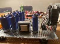
Well after a very sluggish start, I FINALLY soldered my first components onto my power supply PCB. I have what (IN THEORY...) should be my last Mouser order in the way.
For some reason, I was having some 'issue' soldering the 3W resistors on the board. 700 degrees on the soldering iron, nice Kester lead solder. I got beautiful, good solder connections on the rear of the board, but I did not see any solder flow through to the other side. It did this when I soldered the 3W resistors on my ACA (it happened naturally and easily) - but not on this. No issue on the smaller parts (the solder flowed to the other side of the PCB). My fix was to hit the other side of the board with more solder...to ideally fill the holes in the PCB.
I felt like I was leaving the tip on unnaturally long (longer than I have on any PCB), so I didn't want to push my luck. Can anyone else comment on their experience?
you need both temperature and massive soldering tip for anything bigger than small leads and pads
Moi - 480C, 8mm chisel tip
fast - veni-vidi-vici
(think about thermal inertia , that bigger tip gives you)
Moi - 480C, 8mm chisel tip
fast - veni-vidi-vici
(think about thermal inertia , that bigger tip gives you)
Took care with torque wrench during mosfet assembly, @ 0N85.
Regards,
Andy
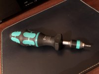
By the way the tool I wrote about ~64 pages earlier.
It have 0.05 Nm steps like 0.85 Nm, 0.9 Nm, 0.95 Nm and so on.
Bits fixation is so neat and all mechanisms work so smooth.
The feel in the hand is so pleasant. Not cheap not luxury, just right.
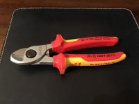
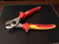
Another tool I also bought is Knipex cable cutter.
Unnecessary. But there was a good discount so I could not resist.. 😀
It cuts the cable like a butter.
This tool is also meant to cut only copper or aluminum conductors.
Steel will damage cutting edges.
Amazing feel just to hold it in my hand. So smooooooth. 🙂
Both
Attachments
Really, reaaly nice. Tools are essential. Makes it all that much easier to achieve good results. Soon you’ll be having a Mighty style Chinese welding machine too 
Everything is more fun with quality tools,
love the Wera Torq driver myself, I purchased one for our company after one of our technicians almost burned down a property by not properly tightening terminal block screws.
love the Wera Torq driver myself, I purchased one for our company after one of our technicians almost burned down a property by not properly tightening terminal block screws.
A quick question: how many hours do a newly bult amp need to be properly burnt in and sound its best?
burnt ....... that can happen in second 
burned-in ...... depending of amp, but for J - count on 50hrs at least
burned-in ...... depending of amp, but for J - count on 50hrs at least
LOL, yes thats true! No open flames nor smoke yet though 🙂
In fact im having trouble getting the mosfets hot enough. Im using the 4U deluxe chassis, a 400VA transformer with 20V secondaries. With a bias of 400mV the mosfets get to around 53 degrees C and the heatsinks around 48. It seems as a small difference? Despite that, I thought 400mV should be the limit in that chassie? I guess Ill need to crank it up to find the bias/ temperature limit.
In fact im having trouble getting the mosfets hot enough. Im using the 4U deluxe chassis, a 400VA transformer with 20V secondaries. With a bias of 400mV the mosfets get to around 53 degrees C and the heatsinks around 48. It seems as a small difference? Despite that, I thought 400mV should be the limit in that chassie? I guess Ill need to crank it up to find the bias/ temperature limit.
Last edited:
Sweden, this time of year, 48C on heatsink?
leave it as is, set to 48C in Summer
damn Vikings ......
leave it as is, set to 48C in Summer
damn Vikings ......
I think he has his amp indoors. Vikings also have electricity now
Edit: 850mA IQ per device is I believe in the 240s sweet spot. Not much need to increase IQ.
Edit: 850mA IQ per device is I believe in the 240s sweet spot. Not much need to increase IQ.
Last edited:
yeah, indoors
22 to 24C
in summer, I believe Vikings are not so soft to keep it on same temp
it isn't healthy anyways, to keep stratospheric difference to outdoor temp, in Summer
that's at least my logic
22 to 24C
in summer, I believe Vikings are not so soft to keep it on same temp
it isn't healthy anyways, to keep stratospheric difference to outdoor temp, in Summer
that's at least my logic
- Home
- Amplifiers
- Pass Labs
- Aleph J illustrated build guide