I retest by keeping the common probe on ground and tested both positive and negative sides and I did get a negative voltage reading on the negative side.
Any ideas why no voltage at r18.
Would it be possible that I have to turn r7 more than 10 x to get a reading?
Any ideas why no voltage at r18.
Would it be possible that I have to turn r7 more than 10 x to get a reading?
Kings...I don’t see minus voltage?
I also measure 20.3 volts at the speaker terminals, if that helps.
Last edited:
Yes....make sure to adjust bias pot measuring voltage across R18....then use offset pot to achieve as close to zero volts across speaker posts
Kingsportal, can we try a few measurements?
Please measure the voltages across D1, R8 and R7. Also, what value are your parts R8 and R7?
Please measure the voltages across D1, R8 and R7. Also, what value are your parts R8 and R7?
I am not able to adjust r7 at all. Its is reading 20volts at the speaker terminals.
R27 is reading 0 volts across r18.
R27 is reading 0 volts across r18.
D1 measures 9.18 v
R8 measure 8.67 v
R8 is 1k ohm
Zener doide for D1 9.1vols 1.3 watt on package
R7 is potentiometer.R8 is 1k ohm
Zener doide for D1 9.1vols 1.3 watt on package
You can measure the voltage across R7 at the holes on each side of the R7 pot.
That voltage is important and should be in the 4 to 5 volt range. If it's too low,
your output mosfets will be off and you will see zero voltage across R18.
That voltage is important and should be in the 4 to 5 volt range. If it's too low,
your output mosfets will be off and you will see zero voltage across R18.
R7 is reading 0 voltsYou can measure the voltage across R7 at the holes on each side of the R7 pot.
That voltage is important and should be in the 4 to 5 volt range. If it's too low,
your output mosfets will be off and you will see zero voltage across R18.
I turned it about 15 times clockwise and nothingCan you try turning R7 and see if you can get a voltage there?
The amp is ice cold from my air conditioning.I turned it about 15 times clockwise and nothing
The heat sinks are not warm at all.
No reading when turned either direction about 50 times. I can hear sort of a click when potentiometer is maxed in both directionsWhat about turning in the other direction?
Dennis has asked the relevant questions. My question is what JFETS do you have installed in Q1A and Q1B? They both should be 2SJ74’s or equivalents. I can’t see it since you have some heat shrink on them. If you don’t have a voltage at R7, my suspicion lies in the JFETS as Dennis had said, you need 4-5V at the gates of the MOSFETS to turn them “on” so they can be biased.
Please confirm what Q2, Q3, and Q4 are as well.
Your N channel MOSFETS appear to be correct in the pictures (IRFP 240).
Best,
Anand.
Please confirm what Q2, Q3, and Q4 are as well.
Your N channel MOSFETS appear to be correct in the pictures (IRFP 240).
Best,
Anand.
Last edited:
Hello and thank you for helping.Dennis has asked the relevant questions. My question is what JFETS do you have installed in Q1A and Q1B? They both should be 2SJ74’s or equivalents. I can’t see it since you have some heat shrink on them. If you don’t have a voltage at R7, my suspicion lies in the JFETS as Dennis had said, you need 4-5V at the gates of the MOSFETS to turn them “on” so they can be biased.
Please confirm what Q2, Q3, and Q4 are as well.
Your N channel MOSFETS appear to be correct in the pictures (IRFP 240).
Best,
Anand.
Q1a and Q1b are Linear systems quad matched jfet LSJ74.
(Aleph J Transistor kit)
Q2. ZTX 550.
Q3. ZTX 450
Q4. ZTX 450
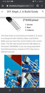
The flat side of j fet faces CBE printed on the board on q2 q3 and q4. I hope they are correct.
What does 24v at the rails mean?
I am getting 24 volts when I check the euro blocks on the power supply board.
My antek 500VA 18V Transformer
does not have a ground cable. It has 2 pair of mains and 2 pair of secondary cables.
Could this be a problem?
Thanks again
Keith
View attachment 954297View attachment 954300
I am also getting 20 volts at the speaker terminals.
View attachment 954301
Last edited:
Jfets should both be lsj74....if the flat side of the ztx is facing you the leg on right is C.
Thats what I did. Just like these in the build guide.Jfets should both be lsj74....if the flat side of the ztx is facing you the leg on right is C.

View attachment 954303
I was able to get this shot of q1aView attachment 954304
Ok picture of q1b looks different
View attachment 954306
Last edited:
It looks like I have Q1A as LSJ74Dennis has asked the relevant questions. My question is what JFETS do you have installed in Q1A and Q1B? They both should be 2SJ74’s or equivalents. I can’t see it since you have some heat shrink on them. If you don’t have a voltage at R7, my suspicion lies in the JFETS as Dennis had said, you need 4-5V at the gates of the MOSFETS to turn them “on” so they can be biased.
Please confirm what Q2, Q3, and Q4 are as well.
Your N channel MOSFETS appear to be correct in the pictures (IRFP 240).
Best,
Anand.
and Q2B as LSK 170.
Is this my issue?
View attachment 954310View attachment 954311
Last edited:
- Home
- Amplifiers
- Pass Labs
- Aleph J illustrated build guide