Thank you both,
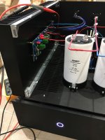
On the side I read MUSE BP, would the BP mean Bi Polar ?
I can’t remember how I ended up buying these...liked the color I guess 😀
What I know is that in doubt, I used the long pin for the + while mounting them.
On the side I read MUSE BP, would the BP mean Bi Polar ?
I can’t remember how I ended up buying these...liked the color I guess 😀
What I know is that in doubt, I used the long pin for the + while mounting them.
NON-POLARIZED are OK to use in place of polar. 🙂 🙂 🙂
Polar are not ok to replace a non-polar. 🙁 🙁 🙁
Any electrolytic in the Aleph J PCB can be used with a non-polar.
Polar are not ok to replace a non-polar. 🙁 🙁 🙁
Any electrolytic in the Aleph J PCB can be used with a non-polar.
Non polars are fine. No need to worry.
Wayne spoke highly of the green Nichicons during a talk at burning amp.
Wayne spoke highly of the green Nichicons during a talk at burning amp.
Thanks a lot 6L6 !
This time I’d rather ask, my F5 project didn’t go that well because I didn’t dare asking...
This time I’d rather ask, my F5 project didn’t go that well because I didn’t dare asking...
I don’t know which component is responsible for what, but that makes an amazingly good sounding amp !
The design of course is quite a masterpiece 😉
The design of course is quite a masterpiece 😉
Pass DIY Addict
Joined 2000
Paid Member
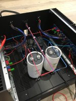
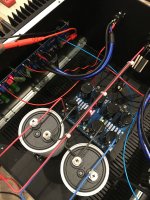
Wow- very nice work! I see some nice caps, clean and neat wiring, a sturdy star ground, and an outboard PSU. Have you experimented with putting the large caps before vs after your CRC in terms of PSU ripple reduction? Might be interesting to see if there is any difference.
Yes the PSU is in another chassis and can be used for other FW amps.
I thought so too that there was some research to do about where to place those enormous caps but to be honest I don’t know how to measure ripple 🙁
I thought so too that there was some research to do about where to place those enormous caps but to be honest I don’t know how to measure ripple 🙁
I even read somewhere something about putting them in the PSU chassis and use the cord as an inductor to make a CLCRC.
Any experience with that ?
Any experience with that ?
Pass DIY Addict
Joined 2000
Paid Member
Measuring ripple is way easier than it sounds. Use your DMM, place the probes across the terminals of the cap (black to black, red to red) and set your meter to it's lowest AC voltage range. Most meters will have something like a 20mV range or lower. This is the one you want to use. Just make the reading - this is your amount of AC ripple on your PSU caps. You'll probably find something on the order of 1-10mV of AC ripple, depending on where you measure and your bias setting.
Measure it on the big white ones, then the smaller ones before your bank of parallel resistors (use the "input" leg of the resistors to measure after your second set of caps), then measure at the output of your CRC boards to see what the final ripple level is. You might find some interesting differences...
As for your last question, this is what I am going to experiment with for my Aleph-J. I have an outboard PSU that is configured as:
750VA toroid
Dual bridge rectifiers
39,000uF caps, 0R1 15w (5x 0R47 3w), 27,000uF for each rail
5-foot long 13ga Power umbilical cord
4x 39,000uF cap (one per rail, per channel) inside the (soon to be completed) Aleph-J
I also have a big pair of 10A 50R inductors that I want to play with. I would like to measure which works best: CRCLC, CLCRC, CCLC, CCRLC, etc. I have some playing around to do over the next few days...
Last edited:
Ok thanks Eric !
I assume the measurements are done with the power off ?
I need to disconnect the amp board too ?
I assume the measurements are done with the power off ?
I need to disconnect the amp board too ?
Pass DIY Addict
Joined 2000
Paid Member
Sorry, measurements need to be made with the power ON - so you also need to be CAREFUL! A slip of the probes will erupt in a shower of sparks... You also need to have the amp boards connected, so that the amp is pulling some juice through your PSU.
This is the only way to measure, but you need to work carefully and in a well-lit area so you can see what you are doing.
This is the only way to measure, but you need to work carefully and in a well-lit area so you can see what you are doing.
I measure 81mVAC at the first big cap, and 60mVAC between the small caps...
But I have no idea what the conclusion is 🙂
But I have no idea what the conclusion is 🙂
Ok no drinking wine and tweaking the amp at the same time then...
🙂
Let's not get crazy now....
Russellc
- Home
- Amplifiers
- Pass Labs
- Aleph J illustrated build guide


