I can't see any bulges.
Do you think I've blown the transformer? Certainly sounds that way. I amsurprised though, thought that would be more sturdy.
Do you think I've blown the transformer? Certainly sounds that way. I amsurprised though, thought that would be more sturdy.
Secondary pairs....the green and blue ones...did you check continuity and make sure they are actually pairs? If not you have a 50-50 shot I guess. I dont think this would distress the transformer the way you say it did, but something to check.
I suppose you can measure the transformer's output voltage and check it. Disconnect from the power supply first of course. Rig up a light bulb tester.
Some of the instructions in the build guide assume you have a working knowledge, or at least sufficient level to see red flags. I have no background in electronics, but I can ID parts, solder well and think projects through. Always get every step of the assembly down in your head. Read the threads, skip over the BS banter and take notes on things that are specific, and problems others had.
Once that's done, go through everything and ask questions if anything is the least bit foggy. Test the power supply first. Then stare at your amp boards and wiring and double and triple check for errors. I cant believe some of the bonehead things I've missed.
When firing up the power supply for the first time, have a variac and or at least a light bulb tester. Once power supply clears, hook it up for full fire up, again with variac and or light bulb tester. If amp fires up successfully on light bulb rig, power down. Dont start setting levels with tester in place. This is where a variac is nice to have...if amp fires up and levels are set, burn in and reset until stable.
As to the transformer, I havent destroyed one yet, but I'm sure it could be done. Testing it NOT hooked up to even power supply is good idea, but variac would be nice to have so you can slowly ramp up voltage. If you havent trashed the transformer, there is definitely a wiring or power supply problem/error somewhere...find it. There is plenty of examples in 6L6's build guides. Look at all of them, the power supplies are basically the same and some guides show things a little different. Watch which wires go where. If transformer checks out, hook up to rectifiers with rectifiers disconnected from the power supply board and measure. If that ok, go over power supply with fine tooth comb.
If power supply then tests fine...NOT hooked up to amp boards, go over boards with fine tooth comb, double check wiring carefully, then test for continuity between mosfet legs and ground. If all is good, hook up amp boards and attempt fireup...with light bulb tester!
Russellc
Last edited:
Just reread your last post. Dont fret reading all those pages. A lot is just banter. Skim for the good parts, especially the places where others are having trouble or have questions. Go through the build in your head until there are no questions left to ask. This knowledge isnt going to magically pop into your head!
I see you say the transformer makes noise even if turned on for the slightest amount of time? Is this while still hooked up, or disconnected from power supply? If still hooked up, disconnect the secondaries and attach them to a secure block like you see 6L6 use for the CL-60 rig. Measure the output of the transformer with no load. If it still acts up, it must be fried. If not, you have it hooked up to something faulty.
You dont have to know everything to have a successful build, but you must be aware of what you dont know, ask questions for clarification. You will find it and learn a lot if you keep your nose to the grindstone.
Next time, test transformer rectifier setup, then power supply, then on to having amp hooked up. Build a bulb tester...
Russellc
Wot, your rectifier connection second attempt is incorrect. It shows the transformer secondary green wire connected to the positive out (notched corner) of the rectifier bridge. Your first attempt looks correct.
The power supply is bipolar in that one output is positive voltage relative to ground and the other output is negative relative to ground. In other words when you measure the voltage with the meter ground probe on the power supply ground, the meter positive probe on V+ output, the voltage reading is positive and when the meter positive probe is on the V- output, the voltage reading is negative. How were you measuring the voltage when you thought that you had measured the incorrect negative voltage?
It could be that you had the power supply wiring correct except for the very small bleed resistor which caused the fuse to blow. You need to install the correct bleed resistor (2.2k 3W) and correct the transformer/rectifier wiring. Then test your power supply alone. Perhaps your transformer is ok. Use light bulb tester and/or variac as previously suggested.
The transformer is OK . Phew.
It measures 19.4volts ac on each pair of green and blue.
OK Can someone please tell me which way the green and blue should be on the bridge?
Being AC does it even matter?
Looking at the picture on the side of the tranny it seems the blue is positive though, so should it be to the left or the right of the red notched positive DC terminal? I am assuming it should be to the left.
I fried one of the bridge recs but the other measures ok.
The bleeder resistors were open circuit.
I don't have a capacitor tester but the caps look ok. It did let out a bit of smoke though so maybe they are time bombs?
I assume the LED cathode side is to the centre of the board as that terminal is on the earth side?
Would the low bleed resistor cause the LED to blow?
The bridge positive and negative are DC and they connect to the power supply board. The transformer secondary connect to the other two bridge connectors. AC does not have polarity. See 6L6's pictures at the beginning of the build guide.
Connecting the transformer secondary incorrectly to the bridge rectifier did not help things.
The long leg of the LED goes to the positive DC. Too low of a resistor in series with the capacity would blow the LED.
Connecting the transformer secondary incorrectly to the bridge rectifier did not help things.
The long leg of the LED goes to the positive DC. Too low of a resistor in series with the capacity would blow the LED.
Last edited:
See this for PS board LED:
diyAudio Power Supply Circuit Board v3 illustrated build guide
Scroll down until you see the section on LED. The LED orientation is the same for both sides (not mirrored).
"The silkscreen markings at the LED pads are slightly obscured, and the break in the circle, indicating where the flat of the LED should go (cathode, negative, short leg) is a little bit confusing. The legs of the LED go as shown. You can also see another link at the top of the PCB where I joined GND together."
Last edited:
Wot, sorry to see so much difficulty for you in powering the J for the first time. Assuming you fuse the primary of a transformer properly you won’t blow it no matter what you do with the load on the secondary side. Learning how to use an ohm meter to troubleshoot a circuit unpowered is something I recommend. That’s what I do when given a choice. Having a schematic in front of you and working through the wiring with an ohm meter is a good way to familiarize yourself with the circuit and to find errors. Since you do this with the circuit unpowered it is safe for you and for what you are working on.
Yes I read this but there is no picture shown. I clicked the link but it goes to some archive with hundreds of pics and no way to find that one.See this for PS board LED:
diyAudio Power Supply Circuit Board v3 illustrated build guide
Scroll down until you see the section on LED. The LED orientation is the same for both sides (not mirrored).
"The silkscreen markings at the LED pads are slightly obscured, and the break in the circle, indicating where the flat of the LED should go (cathode, negative, short leg) is a little bit confusing. The legs of the LED go as shown. You can also see another link at the top of the PCB where I joined GND together."
When I look at my board the circle where the LED's go has a break on both sides so the words don't help. Unless you said the cathode is to the right side of each half board or vice versa. That would seem weird because each half is a mirror in every other way.
Also in the build guide are many descriptions of things with pictures with broken links that can't be seen. Do I have to pay a subscription to see these things?
By the way I didn't connect the green to the DCpositive but I did reverse the dc pos and neg which was probably the worst thing I did.
Also looking at 6L6 pictures of the bridge it's quite hard to see which side the blue and green go to but if it doesn't matter then that's another thing out of the way.
Thanks Ben.
Last edited:
With regard to the power supply:
If I measure connectivity with my multimeter I see that the inner leg of the LED, that is the leg closest to the middle each are directly connected to earth. Surely this would be the cathode leg? And surely this is a mirror pattern?
If I measure connectivity with my multimeter I see that the inner leg of the LED, that is the leg closest to the middle each are directly connected to earth. Surely this would be the cathode leg? And surely this is a mirror pattern?
It could be that you had the power supply wiring correct except for the very small bleed resistor which caused the fuse to blow. You need to install the correct bleed resistor (2.2k 3W) and correct the transformer/rectifier wiring. Then test your power supply alone.
Are you sure about this value? My parts list says they should be 4.7K-10K. 3W.
Now I see I messed that up with a low one as I used the same all the way through.
The dropping resistor was also too low which also blew the LED's.
So here's hoping the right values in there will yield a good result.
Really how dumb can you get?
But I still need to double confirm the direction of those LED's.
2.2k is often the bleeder value used in the Firstwatt power supply. For example,
you can see it in the F4 PS (p14: )
http://www.firstwatt.com/pdf/prod_f4_man.pdf
The value is not exact and is a trade off between how long it takes to
drain the power supply to a safe level vs how much additional load you are
placing on the supply.
you can see it in the F4 PS (p14: )
http://www.firstwatt.com/pdf/prod_f4_man.pdf
The value is not exact and is a trade off between how long it takes to
drain the power supply to a safe level vs how much additional load you are
placing on the supply.
Last edited:
LED is not a mirror pattern, as GND is 24v above V neg.
Think about it for a minute.
2.2k 3w will work well as bleeder resistors.
Think about it for a minute.
2.2k 3w will work well as bleeder resistors.
What 6L6 said.
Recall that for the LED to work, the anode has to be at a positive voltage
relative to its cathode:
Polarity - learn.sparkfun.com
Now have a look at the schematics for the PS board:
https://cdn.shopify.com/s/files/1/1006/5046/files/P-PSU-1V30-schematic.pdf
and you can see that the LEDs are not in mirror image placement.
Pass DIY Addict
Joined 2000
Paid Member
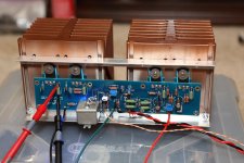
Got one channel of my Aleph-J up and running, but I am having trouble adjusting R27 with any significance. For R27, I installed a 56k resistor with a 20k pot in series as someone suggested a few pages ago instead of the 100k pot.
With the 20k pot maxed out, Vdrop across R18 = 0.542v. With pot turned fully in opposite direction, Vdrop across R18 = 0.523v. There isn't much movement here...
Big green power resistors R6, R7, R18, R19 measure 0.531v, .523v, 0.525v, 0.530v voltage drop.
0R47 / 0.527v drop = ~0.98A per device at 22.3v rails = 19.8w dissipation per device, so each sink is dissipating ~40w of heat.
With thermocouple on my DMM, the hottest spot I can find is the mosfet mounting screw at 56c, hottest spot on the sink is directly adjacent to mosfet at 50c, ambient = 23c. I can live with this temperature for the amp. Thermal interface is Bergquist 1500ST.
Is there any problem with not getting Vdrop across R27 down to 0.400 for bias/AC gain as indicated in post #3 of this thread?
The temp seems OK, but if AC gain is set less than optimally, I'd rather adjust it...
Attachments
Last edited:
Pass DIY Addict
Joined 2000
Paid Member
oops - make that: "Is there any problem with not getting Vdrop across the 0R47 mosfet source resistors down to 0.400v for bias / AC gain..."
LED is not a mirror pattern, as GND is 24v above V neg.
Think about it for a minute.
2.2k 3w will work well as bleeder resistors.
Hi 6L6 and Dennis, are the bleeder resistors a 100% requirement? I built the power supply with the diy kit without the bleeder resistors for my Aleph J project (atleast that’s my recollection) and all is fine. I believe I also read in one of the threads before my build that they weren’t always necessary.
Edit: I just looked at pics of my build and there is indeed a 2.2k 3w resistor there. ����
Last edited:
Hi 6L6 and Dennis, are the bleeder resistors a 100% requirement? I built the power supply with the diy kit without the bleeder resistors for my Aleph J project (atleast that’s my recollection) and all is fine. I believe I also read in one of the threads before my build that they weren’t always necessary.
The idea is the bleeders present a small load so that after power down, the voltage and the charge of the power supply will slowly drain down.
If you have LEDs on your power supply and you find that they stay on
for a while after your power down then they're doing basically the same thing.
Edit: Just saw that you have bleeders.
Pass DIY Addict
Joined 2000
Paid Member
From my perspective, the most important time to have bleeders is when you are actively building and experimenting. If you don't have bleeders installed and your power up your PSU without the amp attached, you run the risk of some surprises when you connect the amp. 2k2 bleeders (mine are 2w and are just fine) will take about 2-3 minutes to drain down a ~22v power supply.
Bleeders probably have less value for a completed/working amp.
Bleeders probably have less value for a completed/working amp.
I guess the bleeders are really for the times when one needs to open and service
the device.
A few years ago I reformed a bunch of caps and left some to discharge on their
own. When I returned a week later they were still holding pretty high voltage.
the device.
A few years ago I reformed a bunch of caps and left some to discharge on their
own. When I returned a week later they were still holding pretty high voltage.
- Home
- Amplifiers
- Pass Labs
- Aleph J illustrated build guide