Pass DIY Addict
Joined 2000
Paid Member
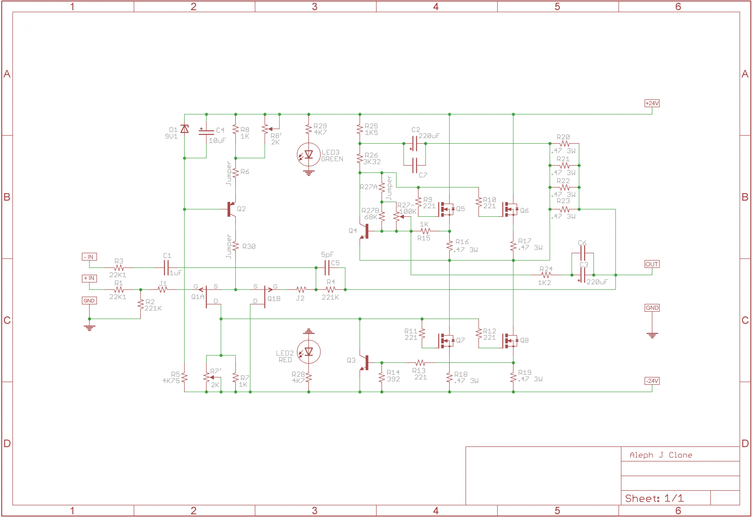
I'm about to begin stuffing my Aleph-J boards and have a question about the input differential. I have two pairs of 74's set aside for this build: one pair matched at 8.45mA and the other pair is matched at 9.73mA.
I presume that by adjusting the R8 pots, I will be able to adjust the bias through the Long-Tailed-Pairs so they match across boards and I won't get channel imbalances. Is this correct, or should I use a quad matched set of 74's?
I presume that by adjusting the R8 pots, I will be able to adjust the bias through the Long-Tailed-Pairs so they match across boards and I won't get channel imbalances. Is this correct, or should I use a quad matched set of 74's?
Hi kstagger,
What voltage across R7 are you seeing?
Thanks,
Dennis
Dennis - sorry for the delay. Work and life gets in the way.
Voltage across R7 is 4.65V, offset is 202mV - no more room for R7 adjustment.
"good" side, where the offset is 1mV, voltage across R7 is 4.63V.
Do I need to change the 1K resistor in parallel to a different value or ?
Hi kstagger,
You wrote: "Do I need to change the 1K resistor in parallel to a different value or ?"
Are you saying that your 'R7' location has both a 2K pot and a 1K resistor?
I don't think you need both. Can you please confirm what parts you have there and their values?
Thanks,
Dennis
You wrote: "Do I need to change the 1K resistor in parallel to a different value or ?"
Are you saying that your 'R7' location has both a 2K pot and a 1K resistor?
I don't think you need both. Can you please confirm what parts you have there and their values?
Thanks,
Dennis
Will do - was looking at the original schematic on the first page - but I'm not sure if the actual build mirrors that. Won't get to it until I get back home tonight.
Hi kstagger,
You wrote: "Do I need to change the 1K resistor in parallel to a different value or ?"
Are you saying that your 'R7' location has both a 2K pot and a 1K resistor?
I don't think you need both. Can you please confirm what parts you have there and their values?
Thanks,
Dennis
Dennis - looking at a blank PCB and a populated one, there is no 1K resistor in parallel with the 2K pot in the R7 position.
ie - only the 2K pot is used for dialing out the output offset.
Hi kstagger,
So a single pot at R7 and you've bottomed it out and have 4.65V across it?
Can you please confirm the value of this pot her?. It almost sounds if you may
have 1K here. (You may want to check the model number of the pot to verify its
value.)
Also, what do you have at R8? Resistor or pot? (And what value?)
Thanks,
Dennis
I confirmed the Bournes pot is 2K - per the datasheet, marked 202 is 2,000 ohms
R8 is a fixed 1K
I'll add the two 2SJ74s are from from Ebay via punkydawg, who has been vetted as selling real parts. But I wonder if the matching isn't all tight enough - ?
R8 is a fixed 1K
I'll add the two 2SJ74s are from from Ebay via punkydawg, who has been vetted as selling real parts. But I wonder if the matching isn't all tight enough - ?
I confirmed the Bournes pot is 2K - per the datasheet, marked 202 is 2,000 ohms
R8 is a fixed 1K
I'll add the two 2SJ74s are from from Ebay via punkydawg, who has been vetted as selling real parts. But I wonder if the matching isn't all tight enough - ?
I mean anything could happen but I bought some Fets from them for a M2 build and they were as advertised.
You shouldn't need super tight matching to get decent offset figure.
Since you've bottomed out the 2k pot, can you perhaps try this? Let the amp warm
up, and then adjust R8 in the opposite direction slowly while monitoring the offset.
(Make a small adjustment and let the offset catch up.)
Since you've bottomed out the 2k pot, can you perhaps try this? Let the amp warm
up, and then adjust R8 in the opposite direction slowly while monitoring the offset.
(Make a small adjustment and let the offset catch up.)
You shouldn't need super tight matching to get decent offset figure.
Since you've bottomed out the 2k pot, can you perhaps try this? Let the amp warm
up, and then adjust R8 in the opposite direction slowly while monitoring the offset.
(Make a small adjustment and let the offset catch up.)
R8 is a fixed 1k resistor right now - but I do have a 1K pot in my stash. So I'll try this over the weekend.
thanks!
The input stage front end CCS (the thing that would be adjusted by R8 if it were a pot) has a very small amount of adjustment from the pot as it's operating point is set mainly by the zener. Which is to say, don't bother installing the pot.
What is your 'bias' set to on the output? Are you measuring 0.35-0.40v across either R18 or R19?
If everything is seeming to be operating normally and you are just running out of pot travel you can add series resistor to the pot, or a bigger pot, but that requires unsoldering and lifting legs
I'd still like to see some photos to see if there's an issue somewhere else...
Yes, pictures will be good. Also measure voltage across R16/R17 and short
the input before you start measuring/adjusting. Have you a second meter
to measure the offset and voltage across, say R18 simultaneously?
the input before you start measuring/adjusting. Have you a second meter
to measure the offset and voltage across, say R18 simultaneously?
Pictures - left to right - of the PCB in question:
https://i.imgur.com/YlWQsE3.jpg
https://i.imgur.com/PITrQPN.jpg
https://i.imgur.com/1cu4Ihp.jpg
With a shorted input I turned the bias down from 385mv to 350mv and began to measure:
R19 - 351mv
R17 - 347mv
output offset: 257mv
I don't have a second meter but can buy one if necessary.
https://i.imgur.com/YlWQsE3.jpg
https://i.imgur.com/PITrQPN.jpg
https://i.imgur.com/1cu4Ihp.jpg
With a shorted input I turned the bias down from 385mv to 350mv and began to measure:
R19 - 351mv
R17 - 347mv
output offset: 257mv
I don't have a second meter but can buy one if necessary.
shoot for desired value of Iq (voltage across source resistors) , fiddling with R27 group ohmic value
then , if output offset is positive (black robe on GND , red on output) you need to either slightly increase ohmic value of R7 group , or slightly decrease ohmic value of R8 group
then , if output offset is positive (black robe on GND , red on output) you need to either slightly increase ohmic value of R7 group , or slightly decrease ohmic value of R8 group
I will try changing R7 to a 5K pot. I suppose a 2.5K or 3K pot would do but I don't see a Bourns # for such a thing. Have to order the part so I will report back.
thanks!
thanks!
I have 5K pots. Where do you live in GR.
Much appreciated but I already made the order - plus I need a new desolder pump anyways. But to answer your question I'm over in EGR, near Breton Village.
Really dumb question here - but I bought the Aleph J transistor kit from DIY Audio and noticed there are two types of supplied zener diodes here. Two 5.1V, and a pair of 6.1Vs the latter listed as optional. Which is the correct one to use and why are they different than the schematic given 9.1V?
I believe when I built the second PCB I grabbed one of the 6.1V or 5.1V zener. Would that cause my offset issue?
I do have some 9.1V that I have from Digikey - and I can't remember for sure but I think I used this for my working side.
I believe when I built the second PCB I grabbed one of the 6.1V or 5.1V zener. Would that cause my offset issue?
I do have some 9.1V that I have from Digikey - and I can't remember for sure but I think I used this for my working side.
Last edited:
- Home
- Amplifiers
- Pass Labs
- Aleph J illustrated build guide