Hi folks
I have some high current chokes and am thinking of using them for an Aleph J PS. Anyone else done this? I have some 10mh .3 ohm 12.5 amp and also some big 10amp 30mh .2ohm. They are big and heavy so I'm thinking a separate PS box. Any opinions on whether it will be worth the effort to go this route? Simulations indicate a perhaps 20db reduction in PS rail ripple.
I have some high current chokes and am thinking of using them for an Aleph J PS. Anyone else done this? I have some 10mh .3 ohm 12.5 amp and also some big 10amp 30mh .2ohm. They are big and heavy so I'm thinking a separate PS box. Any opinions on whether it will be worth the effort to go this route? Simulations indicate a perhaps 20db reduction in PS rail ripple.
that's not just ripple , but also energy storage thing
go for it
if you can , think about LC filter too
go for it
if you can , think about LC filter too
I would like to try this road too, I've found some Hammond 10mH 5A, one for every branch ( 2 per channel ) in a MF Citation 12C in a CLC configurtion. I've read quite enough, people are not especially agree but who did are very happy.Hi folks
I have some high current chokes and am thinking of using them for an Aleph J PS. Anyone else done this? I have some 10mh .3 ohm 12.5 amp and also some big 10amp 30mh .2ohm. They are big and heavy so I'm thinking a separate PS box. Any opinions on whether it will be worth the effort to go this route? Simulations indicate a perhaps 20db reduction in PS rail ripple.
Thanks for the input. I'm wondering if i could use 1 choke in the return line to filter both + and - supplies, as long as the current rating is high enough.
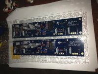
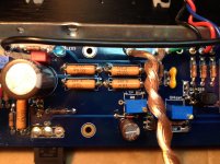
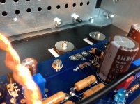
Last night I’ve finished my Aleph J…
First off all I would like to thank to:
- 6L6 for his great building guide
- Zen Mod for his help on every single post
- All other members who has build Aleph J and give generous help
- And finally to Magnificent Mr.Pass
Remarks
After first power on both channels worked without any problems…I didn’t trim anything (didn’t touched trimmers)… Both channels - DC offset 20mV…. Bias 540mV…fantastic….hands on heatsinks – more than 10sec.
To every future builders…. Read all posts, be careful when assembling and most important – measure every single component!!!
Thank’s to all
Toni
Attachments


That looks fantastic! Congrats on a very nice looking and compact Aleph J. Please post your impressions of the sound after you have given it a listen.
Thank you...Sure …Will be interesting to compare it with my beloved Aleph 2 monsters 🙂That looks fantastic! Congrats on a very nice looking and compact Aleph J. Please post your impressions of the sound after you have given it a listen.
Thank'sFugly!

Help, I broke something on Aleph J.
Hello, I've been using my Aleph J for about two months now connected to a pair of MA 7.3 full range speakers with wonderful results.
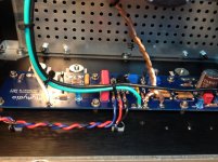
Yesterday, I connected my just completed and biased BA-3 preamp to the Aleph J. Only one channel could be heard. The voice coil of the one silent speaker was fully extended! I shut everything down and opened the Aleph J. One channel of my Aleph has 23vdc on the speaker output!!!!! The other channel is ok. (I will address the BA3 issue in separate post on the BA3 preamp thread).
Could someone help me troubleshoot? What component to test or likely to have failed?
TIA,
John
Hello, I've been using my Aleph J for about two months now connected to a pair of MA 7.3 full range speakers with wonderful results.
Yesterday, I connected my just completed and biased BA-3 preamp to the Aleph J. Only one channel could be heard. The voice coil of the one silent speaker was fully extended! I shut everything down and opened the Aleph J. One channel of my Aleph has 23vdc on the speaker output!!!!! The other channel is ok. (I will address the BA3 issue in separate post on the BA3 preamp thread).
Could someone help me troubleshoot? What component to test or likely to have failed?
TIA,
John
OK, thanks. I will test and post pics. Mosfets Q5,6,7,8 correct? Can I test them while they are soldered and connected to the pcb?first test output mosfets for shorts , then we can proceed
also post some pictures
Attachments
I suggest you have a good close look at the circuitry and wiring. look for anything burnt, disconnected or showing signs of overheating.
Is it possible that your preamp put out some DC or a very large pulse at power up? It is something to consider. The most likely components to fail are those that get hot. If the output FETs check out ok then I would check all the other semiconductors on that board. You can compare readings with the good board if you are in doubt about what your meter is telling you.
P.S. I hope your speaker survived the abuse!!
I suggest you have a good close look at the circuitry and wiring. look for anything burnt, disconnected or showing signs of overheating.
Is it possible that your preamp put out some DC or a very large pulse at power up? It is something to consider. The most likely components to fail are those that get hot. If the output FETs check out ok then I would check all the other semiconductors on that board. You can compare readings with the good board if you are in doubt about what your meter is telling you.
P.S. I hope your speaker survived the abuse!!
Thanks, btw, the speaker "appears" to have survived. I tested it immediately using my AudioSector LM3875 amp. I sounds o.k. Hopefully didn't damage the voice coil.
yes , test them in situ
if something is fishy , desolder it from circuit and check
OK, the in situ test was confusing and inconclusive, so I desoldered / removed them (Q5,6,7,8) and all tested ok.
Other observations:
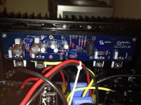
With power applied but with mosfets Q5-Q8, out of the circuit, I measure 24 vdc between V+ and V- but 12vdc between Out and GND (speaker terminals). Should be Zero volts correct?
The now vacant Q5 and Q6 mosfet holes in PCB have 0 volts between gate-drain-source, but Q7 and Q8 have 24vdc between G-D and D-S 😕😕😕
So, what to test now?😕
@Zen Mod, see attached photos.
Attachments
OK, the in situ test was confusing and inconclusive, so I desoldered / removed them (Q5,6,7,8) and all tested ok.
Other observations:
With power applied but with mosfets Q5-Q8, out of the circuit, I measure 24 vdc between V+ and V- but 12vdc between Out and GND (speaker terminals). Should be Zero volts correct?
The now vacant Q5 and Q6 mosfet holes in PCB have 0 volts between gate-drain-source, but Q7 and Q8 have 24vdc between G-D and D-S 😕😕😕
So, what to test now?😕
@Zen Mod, see attached photos.
OK, I'm trying to edit my previous post with the correct values, but there seems to be no edit function.
The previous results were gathered using a 24 vdc test DC power supply that I have.
The following results were gathered with the pcb hooked into the Aleph J 48vdc power supply, and no mosfets installed:
Q5 and Q6 G-D-S 0 vdc.
Q7 and Q8 G-D = 48vdc / G-S = 0vdc / D-S = 48vdc
now , when you already made bigger part of work (with mosfets) , check all small ones in situ and out of it, if needed
however - fastest is - desolder bjt , check it with diode test
input JFets - desolder them and check for Idss on 9V battery or PSU
however - fastest is - desolder bjt , check it with diode test
input JFets - desolder them and check for Idss on 9V battery or PSU
now , when you already made bigger part of work (with mosfets) , check all small ones in situ and out of it, if needed
however - fastest is - desolder bjt , check it with diode test
input JFets - desolder them and check for Idss on 9V battery or PSU
I removed / desoldered bft Q2,3,4 . They passed the diode test. I did not remove the jfets, they are Toshiba, and I can't bear to ruin more components. BTW, now my pcb has no Q2,3,4,5,6,7,8, and when powered up, there is still 24 vdc on speaker output...how can this be 😡
I hate to remove and discard any more of these components in this troubleshooting effort.
Any thoughts????
........ BTW, now my pcb has no Q2,3,4,5,6,7,8, and when powered up, there is still 24 vdc on speaker output...how can this be 😡
......
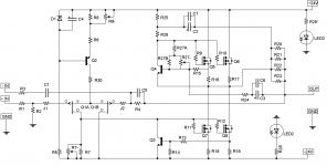
that's normal : R25,R26,R27,R15,R16 and group of 4pcs of WW output resistors ; that's chain conducting minuscule current , but big enough to your DVM measure full rail
remove R16 and you'll got 0 at output , if everything is OK
allthat ref. schm in first post of thread
- Home
- Amplifiers
- Pass Labs
- Aleph J illustrated build guide