The soft start is certainly a good idea, and there is never a decrease in performance using one.
Would the soft start board replace the inrush thermistors totally? Just keep the filter cap?
And for those who have never met Jim in person, he is one of the nicest guys you will ever want to meet. I'm fortunate that he lives fairly close and he was able to drop off the bag of parts. unfortunately our attack dog mauled him and I'm not sure he'll want to come back after that. ;-)
And also special thanks to the rest of the folks who made this possible -- didiet, henrys Papa, and who knows else -- you all rock
-- Jim
V
And also special thanks to the rest of the folks who made this possible -- didiet, henrys Papa, and who knows else -- you all rock
-- Jim
V
Ken, Walter, ma_coule,
Thanks for the recognition. 🙂 It's very much appreciated. 😀
I have always approached this from the view that good illustrations always be helpful, and having a good example to look at will be beneficial for all. This is DIY - there is still lots of information and steps that isn't covered - but this community is smart and people have figured it out.
And with the Aleph J boards, it seemed that if I wanted one, surely others did as well. 🙂
As for soldering technique, thank you. However I attribute it to the liberal use of Kester 44, which has lots of rosin flux and makes it all quite easy - at the cost of leaving lots of residue behind. 🙁
Haha, good old solder with a lot of "plumb and rosin" certainly rocks. The residue is easily coming off with a toothbrush and some isopropanol.
I have soldered panasonic 0.47 3W, however I'm thinking of wirewound type with higher W such as dale cw5 or mills mra5/12. Are they recomended to replace panasonic erx?
Panasonic ERX and ERJ are amongst the best resistors you can get for this application. They are used in the Factory-build Pass Labs amps.
That's great, I'll keep existing panasonic erx. Another questions:
- R9-R12 ; if I understand correctly, I read in some posts that using carbon resistor is good for gate resistor. Is it also applicable here? I'm thinking of riken gold or amrg for this position, eventhough my local seller suggested caddock mk132 which he has stock.
- R8 ; schematic shows 1K while BOM shows bourns 500R, how to see the impact of the changes on this value? I understand bias and offset can be measured using dmm.
R9-12 (Gatestoppers) It's mostly a tube (valve) tradition to use carbon comp resistors as gridstoppers. The gatestoppers can be whatever you have on hand, and honestly any value from about 100ohm-680ohm. I use metal film, line the rest of the amp.
R8 - Place a 1K resistor and omit the pot. The operating point of the CCS is determined by the Zener, and the pot will be necessary in less than 1% of the builds.
R8 - Place a 1K resistor and omit the pot. The operating point of the CCS is determined by the Zener, and the pot will be necessary in less than 1% of the builds.
I can get R27a's to pre-set at 68K, but R7s read around 50 ohms and move +/- 10 ohms with multiple turnings. The Pot at R7 is "W202". Should I be able to pre-set to 1K? If so, am I more likely to have made a soldering mistake or a component misplacement or have a defective part?
W202 is 20 plus two zeros, making it a 2000ohm pot.
In circuit it will probably read much lower; as you have found.
1K is 1/2 of 2K, so run the pot all the way in one direction until it clicks, and then make 12 turns the opposite direction. That will be close enough.
In circuit it will probably read much lower; as you have found.
1K is 1/2 of 2K, so run the pot all the way in one direction until it clicks, and then make 12 turns the opposite direction. That will be close enough.
I kind of figured that it may not measure "in circuit" at the correct value. Thanks for reassuring me.
It doesnt, mine measured 56 ohms! I set mine by measuring from the inside leg to each of the outside two, making sure I got 1K on each....that would center I think? (at least I hope!) I am starting up with a variac, so I think I will be fine if I just go slow and take plenty of time.
Russellc
Russellc
Last edited:
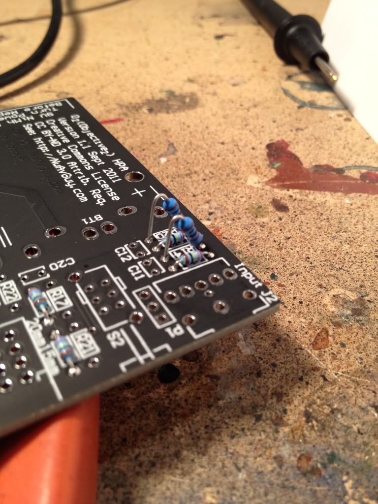
The bigger resistors are mounted soldier-style.
(I thought soldier style was the real term for that... maybe not...)
Just noticed this picture. I had always understood that "soldier style" mounting was straight up and down, usually with a u-bend and a parallel lead.
They guys are leaning just a bit. I call this style "drunken soldier".


Caution for LSJ74
Hi Guys,
Completed my boards and tried powering them up using a light bulb tester (60W bulb). Things didn't go right, so I double checked everything, all resistors are correct, and everything matched build guide. Except that I used the Jfets from the DIY audio store. It appears that the pin outs are not the same as the Toshiba Jfets, and they cannot be oriented as shown in the build guide. So it looks like I need to pull them out and reverse the orientation. Am I reading things correctly ? Do you think that I damaged any thing else when powering up that I should check out ?
Thanks,
PJN
Attachments

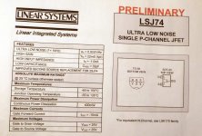
according to datasheet , you oriented them well on pcb
they , most probably , survived if really came to D-S pins swap
check them out of circuit , same procedure as for matching
they , most probably , survived if really came to D-S pins swap
check them out of circuit , same procedure as for matching
- Home
- Amplifiers
- Pass Labs
- Aleph J illustrated build guide