The way I interpret the data sheet I oriented them incorrectly(backwards). I do have a spare set of jets, but I'll try to gently remove the set that I have on the board and see if I can reuse them.
No. Your Jfets are in properly.
A normally functioning Aleph J will pull enough idle current to make a 60W bulb quite bright.
With the bulb in place, check your rail voltages, they should be even from + to GND and - to GNG, although low.
Check DC offset, it should be less than a volt.
If you have those two measurements, replace your bulb with a 100W and try again, the rails should be a bit higher, and the dc offset about the same.
Check your PM.
Hi Zen Mod,
The way I interpret the data sheet I oriented them incorrectly(backwards). I do have a spare set of jets, but I'll try to gently remove the set that I have on the board and see if I can reuse them.
PJN
Look at data sheet again. Those pins you see in the diagram are sticking up. Pins will of course be down when in place.
Now compare them.
Russellc
Last edited:
DOH, You guys are right, I misinterpreted the data sheet.
Thanks for your help.
PJN
Dont ask how I figured that one out. At least you didnt "fix" it....
Russellc
Hi Everyone,
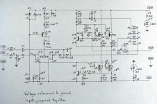
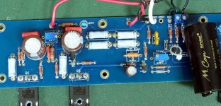
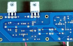
I did get one channel up and running successfully, but I'm having trouble with the other. It doesn't seem to be drawing any power. The rail leds light and I'm getting +/- 24v on the rails to the board with a light buld tester supplying the power, the bulb doesn't glow at all. On the good channel the bulb glowed brightly. I'm getting 24v DC offset at the output, with the inputs shorted. I've triple checked the resistors, all are as spec'd. I've replaced Q1A, Q1B, Q2, Q3, and Q4 with no change. I have a set of mosfets for Q5 - Q8 in reserve but I haven't changed them out yet. I've attached some closeups of the board as well as a schematic showing voltages. Please note that the voltages around R14 are really -24v, and R6 is jumpered with a wire underneath the board. I'd appreciate If you could take a look and see what I've missed.
Thanks,
PJN
Attachments

Hi Itsmee,
I'm reading 0.39v across R7. I've had it preset to 1K before startup, and moved it through it's full travel in both directions with no effect on DC offset. I've also had R27A set for 68K before startup and have moved it through it's full travel in both directions with no effect on bias.
PJN
I'm reading 0.39v across R7. I've had it preset to 1K before startup, and moved it through it's full travel in both directions with no effect on DC offset. I've also had R27A set for 68K before startup and have moved it through it's full travel in both directions with no effect on bias.
PJN
yup , I saw this
but - I'm somewhat lost in that pcb , with several possibilities where shorts are going , where are not going
I believe guys with more personal insight in these pcbs will chime in
though - with continuity test - try all important ( aren't they all ) connections
re-flow (from both sides) all points having vias - maybe you have failed via connection ....... especially if you had trouble to push any part's leg through hole
but - I'm somewhat lost in that pcb , with several possibilities where shorts are going , where are not going
I believe guys with more personal insight in these pcbs will chime in
though - with continuity test - try all important ( aren't they all
) connections re-flow (from both sides) all points having vias - maybe you have failed via connection ....... especially if you had trouble to push any part's leg through hole
Thanks Zen Mod,
I also wrote down the voltages around R 0 and R12 incorrectly Should be 23.9 around R12 and 24 around R10. I've been staring at the schematic for a long while and I can't understand it so far and I'm getting burned out. I'll put things aside to rest for a day, reflow all joints, and replace Q5 - Q8, that way all of the active parts have been replaced. I didn't check any of the caps and maybe I have a bad one that is shorting out so I'll check that out. And give it another whirl and compare the voltages to the good board.
PJN
Hi PJN,
First, always follow ZM's sage advice.
If R7 is set for 1K, then you have 0.039mA flowing through Q1A. Fit a resistor in the R30 position so you can measure the tail current.
A quick way to check if Q1A & B are working, make sure R7-//R7 is set to 1K, and set R27 to minimum bias; short Q1A & B source's to 0V - is there a change in the voltage across R7?
I agree you've got something wrong in that LTP. You do have 8.3 mA at the top (R8) so that's normal, but where is that current going... Your output FET's (Q7, Q8) need 4.5 volts or so from gate to source before they turn on (current flowing). I would check for shorts / open paths around Q1A and B. Do as Itsmee has instructed. If completely stuck I would pull Q1A and B out and measure the Idss of each. Basically you've got to get that ~4.5V across R7 or this puppy ain't working.
Attachments
Last edited:
PJN - what kind of bipolar transistors are you using in your build? BC? ZTX? Something else?
Great question. I once ran across some bipolars that spec'ed the same, but where built with different pinouts. That could ruin your day.
Jim- Can you provide a pic or two of the 4U chassis, with the Aleph J and V3 power supply? I find plenty of pics of portions of builds, often from obscure angles, but I can't seem to find a top-down view showing all of this at once. I understand the 4U chassis is a perfect fit, but how snug is it all once you have the PS, rectifiers, trafo, etc? If one wanted to add soft start and speaker delay, would those boards even fit or, if one were to use riser panels, could they be creatively placed to allow everything to fit in chassis?
Hi Guys,
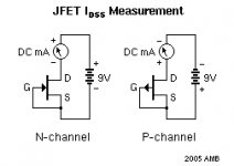
I measured the IDSS of the JFETs just before I replaced them the other day, they both measured 12.51 mA each. The bipolars that I used are Fairchild BC550C and BC560C, they are the exact same types that I used in the good board. I do have some alternative ZTXs on hand though.
I'll follow your advice and report back.
Thanks,
PJN
Jim- Can you provide a pic or two of the 4U chassis, with the Aleph J and V3 power supply? I find plenty of pics of portions of builds, often from obscure angles, but I can't seem to find a top-down view showing all of this at once. I understand the 4U chassis is a perfect fit, but how snug is it all once you have the PS, rectifiers, trafo, etc? If one wanted to add soft start and speaker delay, would those boards even fit or, if one were to use riser panels, could they be creatively placed to allow everything to fit in chassis?
I will be happy to do so, once I'm back in town. I've got all the parts you mention and will be able to assemble that amp configuration when I return.
But the long story made short is this - in order to fit you might have to mount the PSU board on one side and the transformer on the other. (If using the new v3 PSU. ) OR snap the bridges off the PSU and mount them flanking the transformer, or (if using a deluxe) mount the cap section of the PSU on the inside of the faceplate. Please remember that the capacitor section of the PCB should be split only if you have to.
There might not be room to flat mount a transformer and v3 PSU , from front to back, on the perforated baseplate. But I could be wrong, as I am not in front of the chassis at the moment.
If you mount the PSU board on one side and the transformer on the other, it will fit fine. Or you can stack the PSU over the transformer with a few risers.
See the images on the bottom of this page for a few ideas - Deluxe 4U "Jack of all Chassis" (All Aluminum) - Chassis
I measured the IDSS of the JFETs just before I replaced them the other day, they both measured 12.51 mA each. The bipolars that I used are Fairchild BC550C and BC560C, they are the exact same types that I used in the good board. I do have some alternative ZTXs on hand though.
The Idss is fine - the circuit should have it's operating point determined by the CCS, instead of their self-bias current...
If you are using BC, then they are in correctly.
Hi Guys,
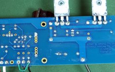
I am a dope, after reflowing all the joints, I noticed that "someone" put the wrong pot in for R7. I had a 500R pot in by mistake instead of the 2K pot. I pulled the pot and plugged a 1K1 that I had on hand and everything comes up fine. I'll need to order another pot because the offset is 200 mV. But on the bright side this has been a learning experience for me. Thank you all for your kind help.
PJN
That's great news!
Everybody will make a mistake or two, the challenge is finding it and setting things correct.
If you didn't want to learn something during this process you could have just bought an Aleph J from Nelson or Reno HiFi, but you have chosen to take the much more interesting road and now - you have yours.
A sincere and heartfelt congratulations! 🙂 🙂 🙂
- Home
- Amplifiers
- Pass Labs
- Aleph J illustrated build guide