Same issue here before i found 6L6´s great info here!
http://www.diyaudio.com/forums/group-buys/241063-aleph-j-kit-parts.html
"The J108 is the exact same die (chip) as a J74, in a smaller plastic package. The pinout is the same, and the only difference is dissipation, which in our application (the differential input pair of the Aleph J) works just fine."
http://www.diyaudio.com/media/pdf/lsj74_09_oct_2009_preliminary.pdf
Hi,
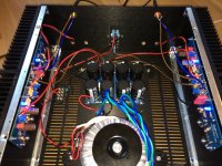
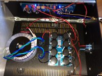
Enclosed are some pictures of the amp.
Wiring is not finalized, but I think you should be able to get the picture of how it's done.
I have after pictures replaced input wires with a shielded ones.
My issue is equal hum in both channels. According to an RTA app. I have on the phone, the hum is at app. 90hz, but appears abit lower to me.
Hum decreased from being audible from 2-3 meters in quiet room, to about 0,5-7 meters after I separated safety ground and PSU ground, latter through CL-60.
Regarding RCA, center pin is wired to in +, outer pin/shield to ground, and ground shorted to in -.
PSU ground is soldered to ST_G2, GND2.2 and GND3.3 is solder together with pin, and GND1 and GND4 are jumpered with a pin.
Right channel GND is wired to PSU negative pcb/rail, and left channel to PSU positive pcb/rail.
Transformer is Antek AN5218.
Edit: Hum is with no source connected.
Any suggestions?
Stefan
Attachments
Last edited:
Thanks Halair, but I think I can twist from here to the moon, and it will still not make any really noticable difference 🙂
I have tried moving around on the wires, and rotating/flipping the transformer on it's side, with no affect.
Do you recognize the chassis? 😉
Stefan
I have tried moving around on the wires, and rotating/flipping the transformer on it's side, with no affect.
Do you recognize the chassis? 😉
Twist more leads? 🙂
Stefan
MARRA: Looking forward to it, knowledge you know 😉
6L6: The hum is almost the same with source connected, as it is with no source connected. A tad less on the latter.
When you say inputs shorted, do you mean closed loop, rca connector center pin to ground?
Stefan
6L6: The hum is almost the same with source connected, as it is with no source connected. A tad less on the latter.
When you say inputs shorted, do you mean closed loop, rca connector center pin to ground?
Stefan
Last edited:
Do you recognize the chassis? 😉
Absolutely 😉
Good progress from your end, hope to follow shortly with my own build 🙄
77
what's happening if you disconnect one channel from PSU , to decrease load
we need to figure out is that hum from ripple , or from inductive drek pickup
what's happening if you disconnect one channel from PSU , to decrease load
we need to figure out is that hum from ripple , or from inductive drek pickup
When disconnecting left channel from psu, there is a slight hum with no souce connected, and no hum with source connected.
Re-connecting left channel and disconnecting right gives no hum with or without source connected.
Both channels have a hint of hiss, really not much, but I guess this is to be expected from a fullrange with no passive filter.
What do I do next to fight this?
Stefan
Re-connecting left channel and disconnecting right gives no hum with or without source connected.
Both channels have a hint of hiss, really not much, but I guess this is to be expected from a fullrange with no passive filter.
What do I do next to fight this?
Stefan
check that RCA jacks and all pcb points (ground?) are isolated from case
sole place where audio gnd can be connected to case is from PSU pcb via NTC to chassis
PSU wires to channel pcb - twist them or not , your choice
signal wires to pcbs - twist them tight and route either fully to sides or fully to mid of case
if noting else helps , make bridge between channel pcbs main gnd points , one fat wire ,direct from one side to other , shortest possible
Thank you Zen Mod for your assistance and advice, but I seem to be missing something.
Last nights test as per your instruction gave a result that to me pointed to the psu as being the culprit- psu ripple?
After doing some reading, I cannot see that this phenomenon, psu ripple, is related to grounding issue, as seems to be what your lates post implies, but then again I might be completely off.. 🙂
I would really appreciate if you or someone else would care to explain the mechanism behind the result I acheived last night, both if it seems related to psu or not.
Fyi, signal cable is shielded now, running comletely to the sides and top, and all pcb's are supported by brass standoffs. Only one audio gnd through CL-60.
Stefan
you already gave an answer in #1190 - that's not ripple ( not sufficiently filtered/smoothed DC , usually as result of bad/too small capacitor)
so , with shielded signal cable , you're getting what ...... ?
so , with shielded signal cable , you're getting what ...... ?
Last edited:
I'm not overly familiar with physical layout of those pcbs , so I can't pinpoint from top of my head where is the culprit
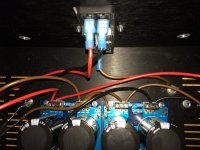
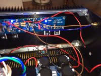
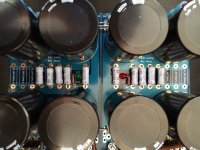
so , give me detailed pics of PSU , say (attach) which PSU cshematic/layout you are using
so , give me detailed pics of PSU , say (attach) which PSU cshematic/layout you are using
Stefan -
Please try this test: Unbolt the transformer and rotate it 90deg so the narrow edge is resting on the chassis floor. If you have a particularly wild transformer this will move the magnetic interference to a place where it will be either much stronger or almost completely gone.
If the hum changes or goes away, it's likely the transformer, if nothing changes, it's likely grounding.
I have used the the UPS V3, and followed 6L6 excellent build guide, without the discrete diode bridge.
Caps are 22.000uf 50 volt Panasonics, R1-8 are 0,47 ohm 3 watts, bleeder 2.2kohm and led with a 3kohm resistor.
6L6: I have already tried this, as well as moving it and the wires around in the chassis as much as possible, with no real audible difference.
So I guess I'm stuck with grounding...
Stefan
Attachments
That was my initial setup, but after separating psu ground through CL-60 from mains earth, the hum decreased with app. 1/3 volume.
Will go through it all tomorrow, re-route, twist and what not.
Stefan
Will go through it all tomorrow, re-route, twist and what not.
Stefan
When you say inputs shorted, do you mean closed loop, rca connector center pin to ground?
Yes.
Are you certain the RCA connectors are not touching chassis? It's worth checking.
I also suggest taking an old Cat5 cable, and using 1 twisted pair inside for the signal wiring from RCAs to PCBs - keep it close to the chassis at all points.
Last edited:
- Home
- Amplifiers
- Pass Labs
- Aleph J illustrated build guide