For Q2, Q3, and Q4 are the flat sides on the left? I had some difficulty transferring the datasheet info since my 3d spatial skills aren't so good at times (bottom view vs top view on the datashet).
It depends on what BJT you are using... The BC go one way, ZTX the other. The silkscreen has no defined flat edge, but the holes for base emitter collector are marked.
It depends on what BJT you are using... The BC go one way, ZTX the other. The silkscreen has no defined flat edge, but the holes for base emitter collector are marked.
They are ZTX450 and ZTX550 from your kit. Any guidance would be appreciated.
They are ZTX450 and ZTX550 from your kit. Any guidance would be appreciated.
If you hold the ZTX's with the flat face towards you and the pins below, then the right hand pin is the collector, middle is base and the left is the emitter.
Do a search on google for images of the ZTX450 pinout (550 Is the same)
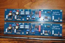
Kevin here is a decent photo semi populated aleph J board. Hope it helps...
thanks
If you hold the ZTX's with the flat face towards you and the pins below, then the right hand pin is the collector, middle is base and the left is the emitter.
Do a search on google for images of the ZTX450 pinout (550 Is the same)
Thank you! I had done the Google searches and read some data sheets, but managed to overthink it and confuse myself with top vs bottom views. Turns out I had it right.
Well I've double checked everything, including resistor values, caps, checked for solder bridges, placements; absolutely everything and it still gave a big offset. 😡
So I had a good think and considered that the only difference with mine was that I've used equivalents for the bjt's because I didn't have enough ZTX450s. I used BC547C's, so I removed them and replaced just Q3 and Q4 with my last 2 ZTX450's and it worked!!!! 😡😡😡😡😡
So the lesson is that BC547 may look like an equivalent but it isn't.
Man did I curse.
ZTX450's on order, I'll update when I've fitted them and also replaced Q2 with ZTX550's
ztx450 and bc547 are equivalents in this case ........ but what isn't - is their pinout
Pinouts were taken into account.
However there is an update, the amp has again faulted, same symptoms as when the BC547's were in and again it lasted less than an hour. I'm really confused.
Could it be oscillating and damaging the bjt's?
same channel again ?
It's happened on both channels, but I only changed the 2 BJT's on one channel, I left the other channel still faulty. No more ZTX's left. I do have BC547's so when I get home I can put them in Q3 and Q4 and see what happens, but I don't hold out much hope.
What is strange is that it works on my lash up for a short while, plays music,no screaming in my cheapo speakers, then the offset starts to climb and quickly gets to a high level.
Does one of the output devices get significantly hotter than the others? From afar it sounds like you may have an issue with the thermal connection to the heat sinks. As one or more devices heat up there is a thermal runaway.
Does one of the output devices get significantly hotter than the others? From afar it sounds like you may have an issue with the thermal connection to the heat sinks. As one or more devices heat up there is a thermal runaway.
I have an infra red thermometer and can read the temperatures at various points on the board and heat sinks. The IRFP240's are all at or about 52C and aren't running away.
I've not done any testing of the bjt's during the period when the amp is working, but after it failed they were all around 30C.
![url], on Flickr](/community/proxy.php?image=http%3A%2F%2F%5Burl%3Dhttps%3A%2F%2Fflic.kr%2Fp%2FnbkJ9Z%5D%5BIMGDEAD%5Dhttps%3A%2F%2Ffarm4.staticflickr.com%2F3699%2F13900506025_065692f57d_o.jpg%5B%2FIMGDEAD%5D%5B%2Furl%5D%5Burl%3Dhttps%3A%2F%2Fflic.kr%2Fp%2FnbkJ9Z%5DIMG_0230%5B%2Furl%5D+by+%5Burl%3Dhttps%3A%2F%2Fwww.flickr.com%2Fpeople%2F110109137%40N03%2F%5Dkevtams%5B%2Furl%5D%2C+on+Flickr&hash=0da8f35cc021a72fd3aa6344fa1ab562)
![url], on Flickr](/community/proxy.php?image=http%3A%2F%2F%5Burl%3Dhttps%3A%2F%2Fflic.kr%2Fp%2FnbkZUK%5D%5BIMGDEAD%5Dhttps%3A%2F%2Ffarm8.staticflickr.com%2F7301%2F13900559023_f84cf85a97_o.jpg%5B%2FIMGDEAD%5D%5B%2Furl%5D%5Burl%3Dhttps%3A%2F%2Fflic.kr%2Fp%2FnbkZUK%5DIMG_0231%5B%2Furl%5D+by+%5Burl%3Dhttps%3A%2F%2Fwww.flickr.com%2Fpeople%2F110109137%40N03%2F%5Dkevtams%5B%2Furl%5D%2C+on+Flickr&hash=29a16fc25de51855e01e1a422eeeae3e)
tHE 2 BOARDS ARE A SOFT START AND A DC BLOCKER.
Toroid is a 1KVA ( I had it in my stash)
Caps are 33,000uF 63V (also in my stash).
Rails are 25V
The 2 IRFP240's turned sideways, are mounted just in case I want to wire them in circuit at a later date.
Last edited:
![url], on Flickr](/community/proxy.php?image=http%3A%2F%2F%5Burl%3Dhttps%3A%2F%2Fflic.kr%2Fp%2FnbkZBv%5D%5BIMGDEAD%5Dhttps%3A%2F%2Ffarm8.staticflickr.com%2F7206%2F13900558023_02026e16c9_o.jpg%5B%2FIMGDEAD%5D%5B%2Furl%5D%5Burl%3Dhttps%3A%2F%2Fflic.kr%2Fp%2FnbkZBv%5DIMG_0232%5B%2Furl%5D+by+%5Burl%3Dhttps%3A%2F%2Fwww.flickr.com%2Fpeople%2F110109137%40N03%2F%5Dkevtams%5B%2Furl%5D%2C+on+Flickr&hash=a2e636f4a5ca231bd461093c23424c26)
![url], on Flickr](/community/proxy.php?image=http%3A%2F%2F%5Burl%3Dhttps%3A%2F%2Fflic.kr%2Fp%2FnbkHKH%5D%5BIMGDEAD%5Dhttps%3A%2F%2Ffarm3.staticflickr.com%2F2824%2F13900504675_f772463005_o.jpg%5B%2FIMGDEAD%5D%5B%2Furl%5D%5Burl%3Dhttps%3A%2F%2Fflic.kr%2Fp%2FnbkHKH%5DIMG_0233%5B%2Furl%5D+by+%5Burl%3Dhttps%3A%2F%2Fwww.flickr.com%2Fpeople%2F110109137%40N03%2F%5Dkevtams%5B%2Furl%5D%2C+on+Flickr&hash=96498b17da53f24b085b9aa16a172532)
Please bear in mind that this has been soldered and re-soldered many times and it is a lash up to test it.
Most of the resistors are 0.25W, others are 0.6W and the big ones are 5W because I had them.
I'm not using the LED's.
Last edited:
for proper level of details , you need to post 1200something pix. pictures
however , I'm not seeing anything wrong , so boyz with actual experience with these pcbs must chime in
however , I'm not seeing anything wrong , so boyz with actual experience with these pcbs must chime in
- Home
- Amplifiers
- Pass Labs
- Aleph J illustrated build guide