I have found out that it is the transformers that makes the buzz. But if I take them out and put power to them, there is no thing!!! Could it be the soft startup board? if so why?
krath;3918896..... said:and put power to them.......
clarify
one thing is feeding resistive load , another is feeding nasty and hungry cap bank, combined with constant current load
It's alive...... 🙂
Thanks to this thread my Aleph J is up and running! Assembled, adjusted and it is running first time. The sound is beautifully detailed and even the bass is a step up from my vintage NAD PE3225.
Special thanks must go to Jim and this excellent build guide, without which I doubt this build would have been completed. As a photographer myself I appreciate the time, skill and equipment required to achieve such detailed and evenly lit close-ups, so next time you are passing through New Zealand - I owe you a beer 😉
Jim is funny guy
only thing , what you can do with him over NZ (or any other earth) is to shoot him with ice-cloud rocket ......... (not exactly recommended)
😉

only thing , what you can do with him over NZ (or any other earth) is to shoot him with ice-cloud rocket ......... (not exactly recommended)
😉
I will hopefully have the chance to get that beer, I would love to lift a pint and hear your favorite album through your favorite amp. 🙂 🙂 🙂
As for close-ups, my biggest secret is using a small- (ish) sensor compact: Depth of field is huge compared to a bigger camera, and they all focus to about 40-50mm.
As for close-ups, my biggest secret is using a small- (ish) sensor compact: Depth of field is huge compared to a bigger camera, and they all focus to about 40-50mm.
Bias
The right channel of my amp is showing 0.44V across R 19 and 0.37V across R18. I guess this is a Vgs mismatch in the output MOSFETs? I matched each MOSFET pair to +/- 0.02V....
Is it bad enough to warrant a new matched pair? The amp is thermally stable even after 6 hours and still sings like a choir of angels... 🙂
The left channel outputs and both CCS pairs are all 0.4 +/-0.1 V.
only if you are sure that source resistors are also superduper matched ............ you need to be concerned .......
if not , just chill
disclaimer - counting that mosfet matching was impeccable
if not , just chill
disclaimer - counting that mosfet matching was impeccable
Hi guys, my aleph j is already a bit of time and it is fantastic that it is suonanado I also want to thank both 6L6 who made this wonderful guide, Zen Mod for its administrative attention and of course the great Nelson Pass, really a genius very generous.
I wanted to rephrase the question that I have done long ago:
what effect it has or should have the bias adjustment on the sound?
thanks
I wanted to rephrase the question that I have done long ago:
what effect it has or should have the bias adjustment on the sound?
thanks
what effect it has or should have the bias adjustment on the sound?
If you set the 'bias' pot to the recommended voltage drop across the output mosfet source resistors, changing it will most directly effect the AC gain of the Aleph CCS. This will also change the bias point.
You can experiment with higher and lower values as you like, with a maximum when the mosfet get to 65C and the heatsink 55C.
As for sound, although you can measure the difference, if you have a distortion meter, I can't hear much difference unless you set things so low they are not in the linear operating point.
In theory, however, more bias is 'better'.
You can experiment with higher and lower values as you like, with a maximum when the mosfet get to 65C and the heatsink 55C.
Is there a lower bound or optimal temperature? I've always seen 25C above room temperature stated as normal/acceptable, but are there other acceptable temperature points?
Any change in sonics due to an adjustment in bias is going to be practically inaudible. I've played with it, and it's really, really subtle.
More telling is that in one experiment I replaced the input Jfets with some Sanyo pieces that measured fully 4X the distortion -- and yet they sounded just fine.
Find a bias point that heats your heatsinks to no more than 55C and rest comfortably knowing that there isn't any more performance you can extract from your amp. Then go buy some new records and enjoy.
A bit less than 20db.
That is with unbalanced input - right?
Is it 6dB more when using balanced input?
Hi everyone,
I am going to set bias and dc offset
Can it be done with passive volume attached?
Or should I remove it first.?
I am going to set bias and dc offset
Can it be done with passive volume attached?
Or should I remove it first.?
Hello all,
Hope someone can help...
I am building two mono J's. The circuits are stuffed and I fired them up.
Channel-1: I have set off-set and bias. The off-set seems to wander between +10 mV and -10mV. I goes up and down.
Observation 1:
Bending Q4 away from R16 seems to change the off-set and seems to lessen the difference in off-set to +/- 5 mV.
Question: is this normal?
Observation 2:
R5 gets quite hot.
Question: is this normal?
Channel 2:
The MOSFETs do not warm up. The PSU is working and the LEDs for the + and - rails are on.
I have compared all resistors with the ones on the working channel and have re-soldered the components. When measuring the voltage on different points on the board against GND, I get some 25V on R16/17/R18/R19. Also, R5 gets rather hot.
Anyone who can help?
Tx in advance, Vranc
obs. 1 - normal
obs.2 - if R5 is according to this schm , do not worry
ref. to gnd ?
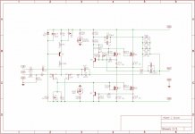
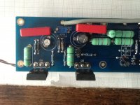
however - give us pictures
obs.2 - if R5 is according to this schm , do not worry
I get some 25V on R16/17/R18/R19
ref. to gnd ?
however - give us pictures
Attachments
- Home
- Amplifiers
- Pass Labs
- Aleph J illustrated build guide