Hi Gang, as 6l6 caught the other night, I reversed both of the zener diodes and on the right channel, rather than removing resistors R1,R2 & R3, for now I soldered jumpers in to populate those resistors to the top terminals of the board. I’m going to replace those resistors with new but I didn’t have any on hand, so I ordered more. Anyways, the left channel is biasing perfectly and the offset is also adjusting beautifully. The right channel is a different story. Using my variac and dialing up slowly with my meter on the far right resister, when I start getting around 50/60 volts, the bias is skyrocketing well over 400-450mv. I’ve tried dialing the bias pot down with no affect. Both pots were set to the half way position prior to soldering them into the board. Can someone point me in a direction? I’m at work and wanted to get this out to the group this way perhaps tonight when I get home I can take a look. With that being said, I have attached the same pic from the other night. The zeners will be pictured backwards and the resistors not populated but they have both been changed.
Attachments
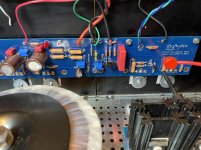
Triple checked all resistor values, especially those in series/parallel/connected with your pots?
All source resistors too high, or just some?
Hugz and kisses.
Andy
All source resistors too high, or just some?
Hugz and kisses.
Andy
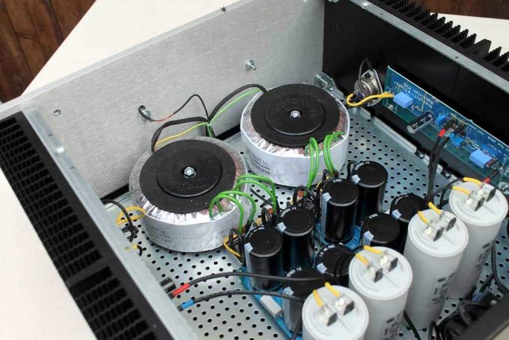
Does the same caution apply to 400VA (AS-4220)?Please don’t use dual 500VA transformers. 500VA is overkill for stereo. Oversized transformers gain essentially nothing except increased chances for back injury when lifting the completed amplifier at the expense of making your wallet lighter. (Use AS-2218 or AS-2220, they are more than big enough and more importantly, shielded.)
I think he is mearly encouraging people to spend their money as wisely as possible. Nothing wrong with big transformers, except they are heavier, cost more, and in this case - are not shielded like cheaper Anteks. Also, bigger trannies are more susceptible to DC saturation, so using smaller ones might be both economical and a soundwise upgrade. Still keeping in line with 2:1 ratio between dissipation and VA. For example, the 5U 400 can dissipate approx 100 watts per sink (I run it even higher), meaning a 200va would suffice. Dual 500, 5 times overkill.
Also, smaller trannies means more room and hence flexibility wrt layout. Win win.
Edit: I chose 2x300, Toroidy. Mighty uses bigger trannies custom made with less vA, meaning less mechanical noise and so on. Basically, it will all work. I always find that following 6L6s advice is good 🙂
And Papa? He uses 1x300va for FW amps. And for his own use, load them even harder without significant penalty.
Regards,
Andy
Last edited:
Fatdad - Two 400VA transformers for dual mono? Total and unnecessary overkill. Fine for single PSU stereo.
Andy’s comments are spot on.
Andy’s comments are spot on.
I might add that even though dual 300s are a bit overkill too, it has the advantage of being split into two stock specced PSUs later if I should choose two build mono blocks, do a biamp config, or simply experiment some more without having to buy more transformers from the get-go. Also, I can put them in a bigger chassis to deliver what is needed for a stock biased 6 deep BA-1 or BA-2 output stage. Plus Mighty uses 2x300, and as I admittedly am hoping for inclusion in his will, I might add that I listen a lot to him as well 
Good luck! Fun hobby, great sound, and great people.
Regards,
Andy
Good luck! Fun hobby, great sound, and great people.
Regards,
Andy
Last edited:
mine are always custom order from great guys at Trafomatic - 300VA, with lowered flux (increased n/V) , static shield, magnetic shield
dual bridge config, of course ..... some of my amps are notoriously loading one rail more than other one
dual bridge config, of course ..... some of my amps are notoriously loading one rail more than other one
tnx
presented in few instances here, by my Webhamster Mikorist
you can see few more details here: SissySIT, another one – Zen Mod Blog
presented in few instances here, by my Webhamster Mikorist
you can see few more details here: SissySIT, another one – Zen Mod Blog
Andy, maybe. I’ll know more tonight when I get home from work. I found a little snippet piece of a wire across the center and end terminal of the bias pot. I removed it and I lowered the pot down to get to 350mv. I shut it down and got the sack. I will know more this weekend for sure. Thanks again because having the board of a few different times I never noticed this. But after I removed it, it seems to be working but I don’t want to rule out a possibly defective pot. Joe
Sounds logical and like you found the culprit. Good work! Hope the result is the same after work 🙂
Aleph J - Dual Mono (Updated Power Drawing)
Thanks 6L6 for your input,
I have finished the Power connections (attached PDF Rev 2), I'm using the PSU Boards as the Star Ground suggested way back in one of the forums (I think that was you 6LS). It made sense to me so I went with it.
Suggestions to make it better are welcomed
Greetings for Miami,
Max
Attachments
OT - Your attention to detail and CAD work are inspiring. Nice addition showing the ties of the GNDs between the V+ and V- sides.
A few minor things.
1) Some people recommend fusing each transformer separately on the primary side with dual mono builds. Up to you.
2) Your transformer shields will generally go straight to chassis / earth. In short, if you choose to use a CL-60 thermistor as a ground lift between signal GND and Chassis / Earth, your purple wire will connect to the chassis / earth side vs. directly to the PSU / Signal GND.
3) If you are going to use Fast-On type connectors for your V+, V-, GND connections from the amp boards to the PSU boards, potentially a more convenient place to put the male connector is on the locations labeled as ST V+, ST V-, and ST G. If your diagram is intended to show location, you have them positioned at the locations generally used for Euro-block style or direct soldering.
I am not 100% sure you addressed 6L6's phasing best practice recommendation. That was a bit over my head, so someone else will have to chime in.
Really impressive.
- Home
- Amplifiers
- Pass Labs
- Aleph J illustrated build guide