KP,
I hope you have the grounds linked on your power supply board. It is not clear in the picture as you have those blue spades there and the large caps are obscuring the view.
Here are examples:
https://files.diyaudio.com/archive/gallery/data/500/medium/PSU211.jpg
https://files.diyaudio.com/archive/gallery/data/500/medium/PSU26.jpg
How everything in the PS should be connected:
https://www.diyaudio.com/archive/gallery/data/500/IMG_2182.jpg
Please thoroughly look through page 1 (and particularly post#1) of this thread:
diyAudio Power Supply Circuit Board v3 illustrated build guide
Best,
Anand.
Last edited:

KP -
Those are certainly not the cleanest joints I've seen. However, I would focus your efforts elsewhere for the time being. Your PSU seems to be functioning properly. Neat idea to swap left to right, but why'd you do that?
I could not find it listed anywhere (but I may have missed it)... do you have a Variac (or similar) and/or a Dim Bulb Tester?
Strongly suggest that you go slowly and one step at a time to get things sorted. It won't take long.
I was hoping to see if the power to the left side of the amp was a problem.KP -
Those are certainly not the cleanest joints I've seen. However, I would focus your efforts elsewhere for the time being. Your PSU seems to be functioning properly. Neat idea to swap left to right, but why'd you do that?
I could not find it listed anywhere (but I may have missed it)... do you have a Variac (or similar) and/or a Dim Bulb Tester?
Strongly suggest that you go slowly and one step at a time to get things sorted. It won't take long.
Since it quit making music I assume thats the issue somehow. Now both boards need help.
Is this wired properly? View attachment 956604
Last edited:
Is this wired properly? View attachment 956604
Hi KP, I'm getting an invalid attachment error with that link. Perhaps you can try attaching the photo again?
Is this section wired correctly ?


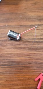
The 2 rectifiers i bought had a leg to solder the wire onto instead of spades like I wanted.
Is this type of rectifier an issue or does it work as a substitute?
The 2 rectifiers i bought had a leg to solder the wire onto instead of spades like I wanted.
Is this type of rectifier an issue or does it work as a substitute?
Last edited:
KP,
A solder type of rectifier can be made to work. Since you’re power supply DC voltages are +/ -21 to 26 V I’m assuming your power supply works fine.
I suspect your main AJ boards, specifically the JFETS.
Best,
Anand.
A solder type of rectifier can be made to work. Since you’re power supply DC voltages are +/ -21 to 26 V I’m assuming your power supply works fine.
I suspect your main AJ boards, specifically the JFETS.
Best,
Anand.
One reason I stayed away from JFETs was the static sensitivity of its gate that makes handling difficult. I never had issues with CMOS chips because they all have built in clamping diodes for sensitive pins.
How would you test JFETs? Are there specific voltages for the input section to confirm normal working?
I am blessed by Lord Murphy, so I am sure I will face all these issues when I start working on mine 🙂
How would you test JFETs? Are there specific voltages for the input section to confirm normal working?
I am blessed by Lord Murphy, so I am sure I will face all these issues when I start working on mine 🙂
Last edited:
KP,
Earlier you wrote that you had 1.8mV across R7 for the left channel board so the jfets
again could be the issue. The soldering looked questionable and there I also saw a fair bit of residue that may have been a problem.
Since you've removed the jfets from both boards, can you test them as Zen Mod suggested in post 6646:
https://www.diyaudio.com/forums/pass-labs/241729-aleph-illustrated-build-guide-665.html#post6675397
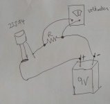
You can use a 9V battery and in place of the ammeter, put in a 100 ohm or so resistor and just measure the voltage drop across the resistor.
For the right channel that smoked, can you see where the damage is? Perhaps you can post photos of the PCB so others may help spot the problem.
Earlier you wrote that you had 1.8mV across R7 for the left channel board so the jfets
again could be the issue. The soldering looked questionable and there I also saw a fair bit of residue that may have been a problem.
Since you've removed the jfets from both boards, can you test them as Zen Mod suggested in post 6646:
https://www.diyaudio.com/forums/pass-labs/241729-aleph-illustrated-build-guide-665.html#post6675397
You can use a 9V battery and in place of the ammeter, put in a 100 ohm or so resistor and just measure the voltage drop across the resistor.
For the right channel that smoked, can you see where the damage is? Perhaps you can post photos of the PCB so others may help spot the problem.
I am trying to figure how to do this test.KP,
Earlier you wrote that you had 1.8mV across R7 for the left channel board so the jfets
again could be the issue. The soldering looked questionable and there I also saw a fair bit of residue that may have been a problem.
Since you've removed the jfets from both boards, can you test them as Zen Mod suggested in post 6646:
https://www.diyaudio.com/forums/pass-labs/241729-aleph-illustrated-build-guide-665.html#post6675397
You can use a 9V battery and in place of the ammeter, put in a 100 ohm or so resistor and just measure the voltage drop across the resistor.
For the right channel that smoked, can you see where the damage is? Perhaps you can post photos of the PCB so others may help spot the problem.
Its reading 9.83 volts with a 93 ohm resistor

View attachment 956783
View attachment 956784View attachment 956785View attachment 956786View attachment 956787View attachment 956788View attachment 956789View attachment 956790View attachment 956791
I measured all 4 jfets.
Attachments
Last edited:
I'm finding it difficult to get some parts in the UK, the Wima mkp caps for example. Any obvious replacements?
I am trying to figure how to do this test.
Its reading 9.83 volts with a 93 ohm resistor
View attachment 956781
View attachment 956783
View attachment 956784View attachment 956785View attachment 956786View attachment 956787View attachment 956788View attachment 956789View attachment 956790View attachment 956791
I measured all 4 jfets.
most pics not working
KP,
Most of your photos aren't showing up (invalid link) and the jfets aren't in the two I can see.
I've attached a drawing of the setup. The voltmeter should show a voltage
proportional to the Idss of your jfet. For example, with R=93 ohms and
if the Idss of the jfet is 8mA then you should see about 0.74V ( 93 x 0.008) across the resistor.
Attachments
Ok Dennis finally home from work.KP,
Most of your photos aren't showing up (invalid link) and the jfets aren't in the two I can see.
I've attached a drawing of the setup. The voltmeter should show a voltage
proportional to the Idss of your jfet. For example, with R=93 ohms and
if the Idss of the jfet is 8mA then you should see about 0.74V ( 93 x 0.008) across the resistor.
Thank you for the diagram.
JFETS measure : 1 pair .744v and the other pair .745v
Is this is what we would expect?
So, with R=93 ohm, you measured all four jfets and got 0.744V, 0.744V, 0.745V and 0.745V.
This is good. You have 4 well-matched jfets with Idss at 8mA. If you got the 7-9mA quad from punkydawgs then this is right down the middle.
So the jfets are probably fine.
Did you spot anything on the PCB that smoked?
This is good. You have 4 well-matched jfets with Idss at 8mA. If you got the 7-9mA quad from punkydawgs then this is right down the middle.
So the jfets are probably fine.
Did you spot anything on the PCB that smoked?
I could not find anything that looked smoked.So, with R=93 ohm, you measured all four jfets and got 0.744V, 0.744V, 0.745V and 0.745V.
This is good. You have 4 well-matched jfets with Idss at 8mA. If you got the 7-9mA quad from punkydawgs then this is right down the middle.
So the jfets are probably fine.
Did you spot anything on the PCB that smoked?
View attachment 957052View attachment 957053
View attachment 957054View attachment 957055View attachment 957056View attachment 957058
I did notice the circle around the pad of a jfet has come off after desoldering the j fets a couple of times. The circle still is the on the back of the board.
View attachment 957060
Last edited:
I suspected it was the led that smoked but I just connected the boards to 9v battery and all the leds worked.
Dang getting ready for work.KP,
None of your photos are showing up.
Will post later tonight
- Home
- Amplifiers
- Pass Labs
- Aleph J illustrated build guide