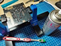
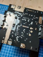
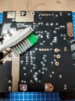
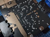
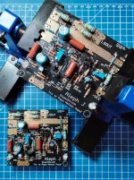
GBR - either short or 10-15R
if you forget it, you'll get bzzzzzzz
edit: solder mosfets only when everything is firmly bolted on heatsinks
if you solder them prior to mounting, there is always some rotation of mosfet body while you're bolting it
which puts mechanical strain on mosfet pins; in that case you need to resolder them, but even then you'll getting just partial release of mechanical strain
Last edited:
Thanks Choky. For mosfet I'll follow 6L6's superb tutorials.
For Greedy Boy Resistor 😀 I'd like to have an advice.

For Greedy Boy Resistor 😀 I'd like to have an advice.

Will do
Looking great! Love the board in black! Can't wait to hear your thoughts on it after it's playing music!
Mine has been getting hours of love every day.
Last edited:
New Jfets coma in and fixed the problem of no voltage across R18 on both boards.
I was able to set Bias and DC offset on the left. So yay for me.
Now the right channel is not adjusting when turning the Bias or the DC offset. The heating on the right side is noticeably warmer than the other side. The R 7 pot is measuring 5.5 volts.
When the amp gets warm after just a few minutes R17 is starting to turn a brownish color and I killed power because I started to smell a component heating up.
I replaced R17 and again had to shut things down because the new R17 was doing the same thing.
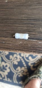
Any ideas where to go next?
What are the Bias and DC offset pots not adjusting?
I was able to set Bias and DC offset on the left. So yay for me.
Now the right channel is not adjusting when turning the Bias or the DC offset. The heating on the right side is noticeably warmer than the other side. The R 7 pot is measuring 5.5 volts.
When the amp gets warm after just a few minutes R17 is starting to turn a brownish color and I killed power because I started to smell a component heating up.
I replaced R17 and again had to shut things down because the new R17 was doing the same thing.

Any ideas where to go next?
What are the Bias and DC offset pots not adjusting?
Last edited:
KP,
Make sure *none* of the 3 pins on MOSFETS Q5-Q8 have a connection to ground. Since you have been manipulating these boards, unscrewing/screwing them, you want to make sure that the back of the MOSFETS which is connected to the drain pin isn’t accidentally grounded due to a break in your insulation (Mica/Keratherm/etc...).
See Step#6: Building: Amp Boards on Heat Sinks
Best,
Anand.
Thank you!KP,
Make sure *none* of the 3 pins on MOSFETS Q5-Q8 have a connection to ground. Since you have been manipulating these boards, unscrewing/screwing them, you want to make sure that the back of the MOSFETS which is connected to the drain pin isn’t accidentally grounded due to a break in your insulation (Mica/Keratherm/etc...).
See Step#6: Building: Amp Boards on Heat Sinks
Best,
Anand.
I will check it out.
I'm almost about to connect a new Aleph J to the power supply.
So I turned on the new PSU and tested the output.
I am using a pair of bridge rectifiers which I expected to be good.
But although the transformer produces 18V AC I was getting 60V DC from these units.
So I hooked up another set which is putting out 18V DC and when plugged through the PSU I'm getting a very nice 24.5V DC on each output side and my green LED's are illuminating well.
I didn't know you could get such a different voltage from the wrong pair of bridge rectifiers. They were rated at 1000Volts, maybe that's why. Can anyone explain this?
Learn something new almost every day.
Tomorrow I will hook up the amp boards. Wish me luck.
your measurements were wrong, or you got wiring in first instance wrong
that difference is not possible, whatever type of Graetz bridge you did use
that difference is not possible, whatever type of Graetz bridge you did use
ZenMod, with the utmost respect, of which I have an enormous amount for you, it is wired exactly the same now as before with just the difference of the Bridge Rectifiers.
I was totally surprised when I found this so I measured and re-measured until I was quite certain .
Tomorrow just for fun I will refit them and show you the readings. Since both sides read the same I am assuming that these rectifiers are not actually faulty.
They were these:
Mouser No: 625-GBPC3510-E4
Mfr. No: GBPC3510-E4/51
Desc.: Bridge Rectifiers Bridge Rectifiers 35 Amp 1000 Volt
Last edited:
no disrespect meant, I'm often enough making silly mistakes, so no way of taking my self too serious and start preaching around 🙂
tech. wise - there is no possible malfunction of Graetz bridge , that it acts as voltage doubler
tech. wise - there is no possible malfunction of Graetz bridge , that it acts as voltage doubler
Just load the DC side of the BR with something like a 2K resistor and repeat the measurements... I think you're mixing the secondary wires... but the resistor will help here.
Tomorrow I'll take photos of the way it's wired and the voltage output.
You guys say this isn't possible so if I repeat the experiment maybe then you'll believe me.
You guys say this isn't possible so if I repeat the experiment maybe then you'll believe me.
I'm almost about to connect a new Aleph J to the power supply.
So I turned on the new PSU and tested the output.
I am using a pair of bridge rectifiers which I expected to be good.
But although the transformer produces 18V AC I was getting 60V DC from these units.
So I hooked up another set which is putting out 18V DC and when plugged through the PSU I'm getting a very nice 24.5V DC on each output side and my green LED's are illuminating well.
I didn't know you could get such a different voltage from the wrong pair of bridge rectifiers. They were rated at 1000Volts, maybe that's why. Can anyone explain this?
Learn something new almost every day.
@Wot,
First and foremost, please don't connect your Aleph J's to any power supply until you have verified without a doubt, that you are achieving +/- 22VDC to +/- 28VDC. There is a risk to damaging the JFETS on your Aleph J if the rectified DC voltages are too high.
Next, on the transformer in question, please show us the label on the transformer itself, the primary wires and the secondary wires. Make sure you follow the labels carefully. In particularly make sure that the secondary wirings (which are in pairs) are continuous with one another, ie. they have continuity (0 ohms on your multimeter). Identify that first. Twist those pairs together. You should have two sets of pairs when done.
Next, if your primaries were originally specified for 110V or if you have dual primaries and you wired them for 110V and you fed it from a mains voltage of 220V to 240V AC as is common in Oz, then the output on your secondaries would be double. You wouldn't achieve 18V AC or close to it, it would be 36V to 40VAC. If you rectified that using your bridge rectifiers you will get between 50-60V DC.
On smaller household appliances, this can be disastrous, destroying the appliance itself due to current overload issues.
For toroids, it depends on how it was designed. If it was a toroid that was designed with dual primaries to work on most of the world AC mains voltages, no harm should be done.
But be careful and if you don't have a Variac already, invest in one. It helps in diagnosing these oversights.
Like ZM said, it's highly improbable that your bridge rectifiers are to question, especially since we have no way of ascertaining from your original post on how you wired up the toroid transformer, how you connected the toroid transformer to the bridge rectifiers and how you connected the bridge rectifiers to the PS board (assuming the PS board was built properly with a proper ground reference in the first place).
Pictures will help. Tremendously. 😉
Best,
Anand.
Last edited:
Peppennino,
1/4 watt should be enough for GBR.
I don't know of Variacs available to you where you live, but here in the US, I purchased this one and I am happy with it:
Bench Top 20 Amp Variac Variable Auto-Transformer with LCD Digital Display
Best,
Anand.
1/4 watt should be enough for GBR.
I don't know of Variacs available to you where you live, but here in the US, I purchased this one and I am happy with it:
Bench Top 20 Amp Variac Variable Auto-Transformer with LCD Digital Display
Best,
Anand.
- Home
- Amplifiers
- Pass Labs
- Aleph J illustrated build guide

