I had to go and recheck it all because I know it's right now but I couldn't get the other Bridge Rectifier to read 60V DC again.
This leads me to apologise to Zen, sorry mate , but I really saw the meter doing that to me. No idea how or why.
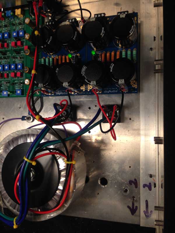
Anyway I'll show you what it looks like and that I've got the right volts to proceed with hooking up the amp boards.
This leads me to apologise to Zen, sorry mate , but I really saw the meter doing that to me. No idea how or why.
Anyway I'll show you what it looks like and that I've got the right volts to proceed with hooking up the amp boards.
@Wot,
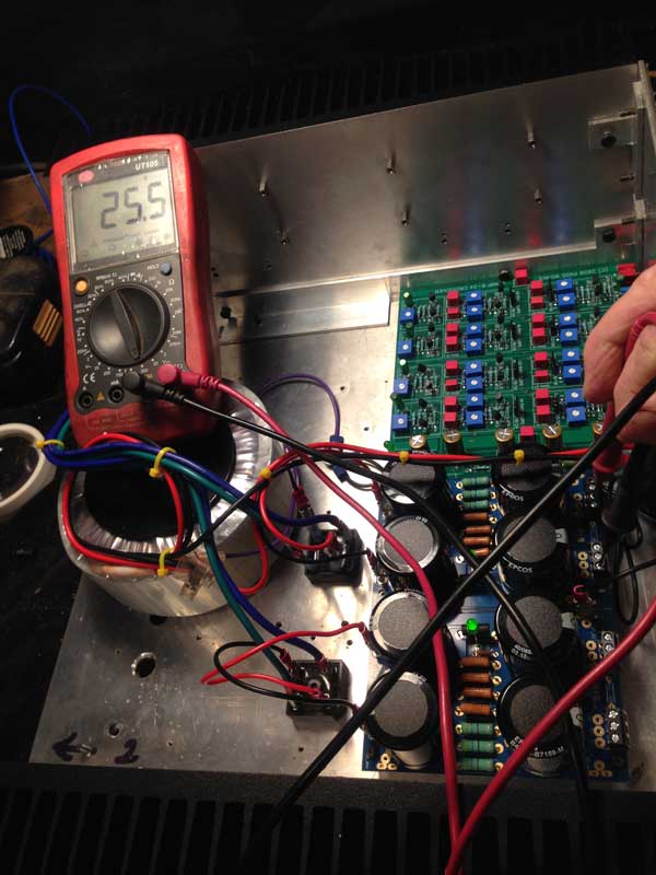
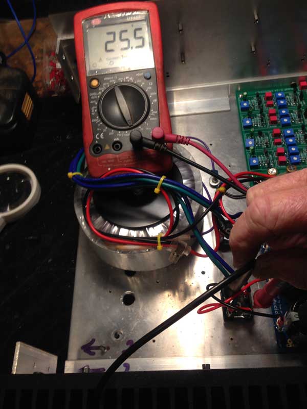
When measuring DC voltages, make sure you have the red lead of your DMM connected to the (V+) output on the power supply and the black lead connected to (GND). That should be your positive voltage rail reading.
For your negative voltage rail reading, connect the red lead of your DMM to the (V-) output of the power supply and the black lead to (GND).
If you connect the red lead of your DMM to (V+) of your power supply output and black lead of your DMM to (V-) of your power supply output, you will measure the total voltage across positive and negative voltage rails. You can get a 50V or 60V reading that way.
The DMM measures voltage potentials.
I'm squinting and I don't see a (-) 25.5 VDC measurement in your pictures above, only (+) 25.5 VDC.
Best,
Anand.
Last edited:
yup, agree
besides understanding, that's procedural thing - in this context - black probe always on GND
besides understanding, that's procedural thing - in this context - black probe always on GND
Your explanations are very helpful!@Wot,
When measuring DC voltages, make sure you have the red lead of your DMM connected to the (V+) output on the power supply and the black lead connected to (GND). That should be your positive voltage rail reading.
For your negative voltage rail reading, connect the red lead of your DMM to the (V-) output of the power supply and the black lead to (GND).
If you connect the red lead of your DMM to (V+) of your power supply output and black lead of your DMM to (V-) of your power supply output, you will measure the total voltage across positive and negative voltage rails. You can get a 50V or 60V reading that way.
The DMM measures voltage potentials.
I'm squinting and I don't see a (-) 25.5 VDC measurement in your pictures above, only (+) 25.5 VDC.
Best,
Anand.
OK I fired her up.
Zeroed the offset but I can't get the bias to move from .1mv.
I admit I forgot to set that trimpot to 68K before installing it.
Both sides behave the same so whatever I've done I did to both.
Where do I look please?
Zeroed the offset but I can't get the bias to move from .1mv.
I admit I forgot to set that trimpot to 68K before installing it.
Both sides behave the same so whatever I've done I did to both.
Where do I look please?
Is that wired for a single-ended input? Or balanced input? If single-ended input, install a link between - IN and GND
Last edited:
Don't have that link on my other Aleph which works perfectly. What does that mean? The input is a pair of RCA jacks from either a DAC or a turntable preamp.
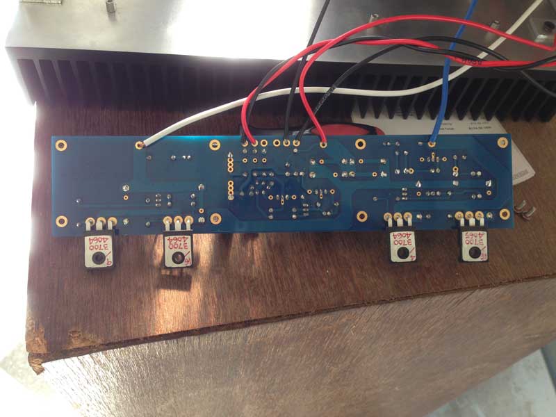
The photos are of such a low resolution that it is impossible to see anything...
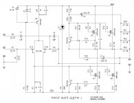
The circuit diagram has 3 voltage values that are important... are they correct?
Across R8 = 8.3V (sets the input JFETs current)
Across R7 = 4.3V (turns the gain MOSFET's on)
Accros CCS MOSFET's = 4.3V (turns to CCS MOSFETs on)
The circuit diagram has 3 voltage values that are important... are they correct?
Across R8 = 8.3V (sets the input JFETs current)
Across R7 = 4.3V (turns the gain MOSFET's on)
Accros CCS MOSFET's = 4.3V (turns to CCS MOSFETs on)
Should I suspect the Jfets? I have a spare set. It just seems unlikely that both boards would behave exactly the same from a faulty component unless they were all faulty.
I bought the Jfets a few years ago from Punkydawg so I was not expecting to have any trouble with them. They are labelled J74 BL 4C. I was very careful using a heatsink clip when soldering them in.
I didn't use that clip for the mosfets. Maybe I cooked them? I have another set of those as well.
I bought the Jfets a few years ago from Punkydawg so I was not expecting to have any trouble with them. They are labelled J74 BL 4C. I was very careful using a heatsink clip when soldering them in.
I didn't use that clip for the mosfets. Maybe I cooked them? I have another set of those as well.
The bias is zero because the MOSFETs are not turned ON... you'll have to do some measurements.... or just knock yourself out and start replacing input JFETs...
The photos are of such a low resolution that it is impossible to see anything...
The circuit diagram has 3 voltage values that are important... are they correct?
Across R8 = 8.3V (sets the input JFETs current)
Across R7 = 4.3V (turns the gain MOSFET's on)
Accros CCS MOSFET's = 4.3V (turns to CCS MOSFETs on)
Last edited:
R8 = 8.47V, R7 = 3.24
R8 = 6.5V,R7=3.25
What is CCS Mosfets?
The outer terminals of the mosfets measure 3.25 on the front pair and 1.36 for the left rear pair and 1.89 fot the other rear pair.
R8 = 6.5V,R7=3.25
What is CCS Mosfets?
The outer terminals of the mosfets measure 3.25 on the front pair and 1.36 for the left rear pair and 1.89 fot the other rear pair.
Don't have that link on my other Aleph which works perfectly. What does that mean? The input is a pair of RCA jacks from either a DAC or a turntable preamp.
That means that the red wire is the input signal hot wire, and the black wire that is connected to - IN is actually the ground potential wire.
R8 = 8.47V, R7 = 3.24
R8 = 6.5V,R7=3.25
What is CCS Mosfets?
The outer terminals of the mosfets measure 3.25 on the front pair and 1.36 for the left rear pair and 1.89 fot the other rear pair.
CCS MOSFET's are two MOSFET's shown in the upper half of the circuit diagram, CCS = constant current source.
The voltage drops are insufficient => the MOSFET's are OFF => no bias.... make sure that:
1. Q2 is the correct part (ZTX550) and it was inserted & soldered properly
2. R8 is 1K, R7 is 1K
3. Input JFET's have to be of the correct flavour, which it seems they are... from your previous post
4. Make sure the Zener is 9.1V type and it is inserted correctly; the right way around.
higher-res photos would help as well...
EDIT: the circuit diagram I've been referring-to, is attached
Attachments
Last edited:
1. Q2 is definitely correct
2.R8 and R7 are both 2K which was in my original BOM.
3. JFETS are correct but maybe they are the problem
4.I checked the Zener and it's the right way around. I'll have to go back through the Mouser order to make sure it's the right size. It looks the same as in the working amp.
More pics tomorrow. Thanks.
Edit, Checked that order and it is the 9.1V Zener. I'll triple check it's the right way around tomorrow.
Last edited:
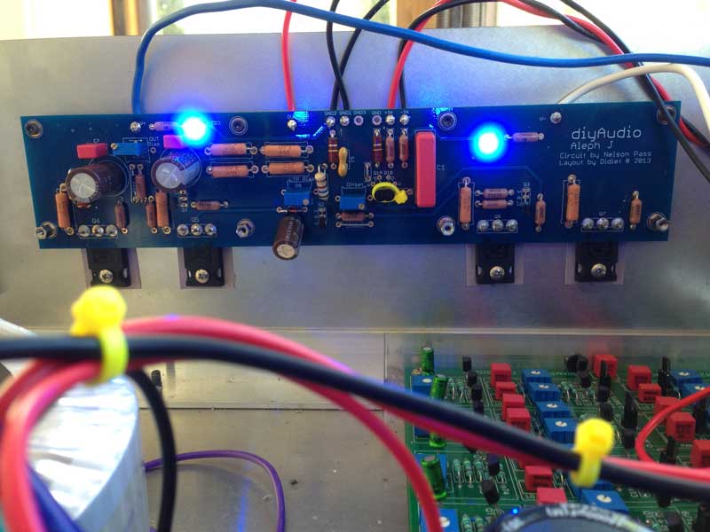
Please post which schematic you've used to stuff your boards.
I see a resistor in place for R6, I cannot determine its value from your pictures. In the most common schematic used (first post of this thread) with those board / schematic designations, R6 is a jumper. It is not a 68k resistor as in Extreme_Boky's posted schematic. Double check that and post back.
In addition, if you installed a 2k pot as R8', did you center it / measure it prior to installation to reach an approximate 1k measurement? I'd suggest simply replacing it with a fixed value 1k resistor, but it's not strictly necessary to solve your issue.
The 6.5V across R8 is also a bit unusual since it should just be the zener voltage minus about 0.7. Can you directly measure the voltage across the zener?
Anand i took out the right board , carefully inspected keratherm. I cleaned the heat sink with alcohol. When I turn on after a minute I can smell the heating on the right side.Thank you!
I will check it out.
R17 seems to be overheating by the looks of it. Perhaps I should have replace it again.
Upon inspection during the Jfet replacement twice the soldering iron slightly melted the R7 top part of the blue case. Could this be the problem?


Troubleshooting question.
If R7 potentiometer is bad, seen in this picture, would it prevent R27 from being able to adjust bias voltage? I have accidentally touched it with the soldering iron when swapping Q1A and Q1B twice. When turning on the amp I am getting 400 MV at R18. This number begins to rise quickly when the amp is on and that is causing R17 to overheat.
Adjusting R27 potentiometer does not reduce the voltage at R18 as it is supposed to.
- Home
- Amplifiers
- Pass Labs
- Aleph J illustrated build guide