Well the toshiba transistors came in.Yup, flat side to flat side.
Hopefully you'll get the replacement before the long weekend. 🙂
I installed them quickly with excitement.
The right channel went according to plan with the bias adjustment and the DC offset.
Then I moved to the left channel and the bias adjustment went ok but the DC offset the meter kept dumping around but it was hovering near 0 give or take a couple milli volts. So I turned things off and hooked up my speakers. When I turned on the amp I heard scratching from the left channel and the right side was music at last.
I am curious so I started taking pictures and the right channel has matching description of J74 BL4C. Keep in mind this side was making music.
However upon inspection the left side was J74BL9G.
Is this the culprit yet again?


What is the difference between IRFP150MPBF and IRFP150NPBF?
Infineon's website has two different datasheets for the two different parts. Perhaps careful scrutiny will reveal all of the differences between them
Semiconductor' '&' 'System' 'Solutions - Infineon Technologies
Semiconductor' '&' 'System' 'Solutions - Infineon Technologies
One difference appears in the first one-third of page one, on both datasheets. Maybe there are more than one difference.
"4C" and "9G" are just different lot codes and should not have an effect.
Just to confirm: The right channel is playing but you only have scratching sound from the left?
Just to confirm: The right channel is playing but you only have scratching sound from the left?
Yes that is correct. I turned off the amp and came back a few minutes later and now the left channel that was scratching is now silent. I go back and remeasure bias pot to R18 and now zero it reads zero volts again."4C" and "9G" are just different lot codes and should not have an effect.
Just to confirm: The right channel is playing but you only have scratching sound from the left?
View attachment 956360
Right side is okView attachment 956361
Last edited:
Well the toshiba transistors came in.
I installed them quickly with excitement.
The right channel went according to plan with the bias adjustment and the DC offset.
Then I moved to the left channel and the bias adjustment went ok but the DC offset the meter kept dumping around but it was hovering near 0 give or take a couple milli volts. So I turned things off and hooked up my speakers. When I turned on the amp I heard scratching from the left channel and the right side was music at last.
I am curious so I started taking pictures and the right channel has matching description of J74 BL4C. Keep in mind this side was making music.
However upon inspection the left side was J74BL9G.
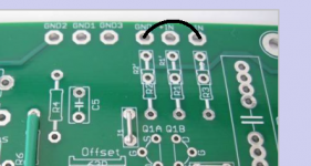
Is this the culprit yet again?View attachment 956333View attachment 956334
that is bad soldering of JFets
too much solder, thinking that you maybe scorched something (heated them too long, trying to push solder too much; there is misconception often, that each and every through-hole part necessary must have same amount of solder on both sides of pcb; more critical for high current parts, but for small ones mostly irrelevant - metalisation of pad holes is glorious thing, per se)
resistors beside are looking as neater soldered - nice concave forms
edit: on second look, resistors are similarly soldered
post better pics, where Boyz can see all details
if nothing suspicious can be found, desolder (quick and efficient!) JFets and check them with simple matching jig
9V battery will do as voltage source
Attachments
Last edited:
On the right side rectifier there is continuity when testing diagonally across on the AC side with each other and the DC side with each other. This side is working and making music.Yes that is correct. I turned off the amp and came back a few minutes later and now the left channel that was scratching is now silent. I go back and remeasure bias pot to R18 and now zero it reads zero volts again.
View attachment 956360
Right side is okView attachment 956361
On the left channel rectifier I have continuity on the AC corner to corner diagonally but no continuity on the DC side corner to corner.
This channel is not playing music.
Any input would be appreciated.


View attachment 956371
Last edited:
remove both rails from channel pcbs, test PSU voltages first, confirm +24(ish)Vdc, -24(ish)Vdc
That is a brain teaser!Infineon's website has two different datasheets for the two different parts. Perhaps careful scrutiny will reveal all of the differences between them
Semiconductor' '&' 'System' 'Solutions - Infineon Technologies
Semiconductor' '&' 'System' 'Solutions - Infineon Technologies
One difference appears in the first one-third of page one, on both datasheets. Maybe there are more than one difference.
The only difference that I could find was with the Continuous Drain Current which is 39A for N vs 42A for M (from Mouser product specs). Datasheet for N on infineon is from IRF!
From the product images, the package identification looks different. 247AC vs 247AD. Anybody knows the difference between the two? I just ordered one and I am sure I need the other one 🙂
I'm not sure what the rails are?remove both rails from channel pcbs, test PSU voltages first, confirm +24(ish)Vdc, -24(ish)Vdc
When placing probes on the power supply board euroblock connector screws i get 21.9 volts on positive to ground and negative to ground on both sides.
R7 measures only 1.8 mv on left.
R7 measures 4.82 on the right.
when black probe is on GND, can you confirm two power wires coming from PSU to channel pcb having +21.9Vdc and -21.9Vdc?
post better pictures, so we can see properly entire pcb (and all of them, including xformer and PSU pcb), with wires and everything
post better pictures, so we can see properly entire pcb (and all of them, including xformer and PSU pcb), with wires and everything
Kinda tricky photography but I think I got a good shot.when black probe is on GND, can you confirm two power wires coming from PSU to channel pcb having +21.9Vdc and -21.9Vdc?
post better pictures, so we can see properly entire pcb (and all of them, including xformer and PSU pcb), with wires and everything


View attachment 956397
Last edited:
I am using XLR and grounded it to chassis on a screw next to xlr input.An observation.. When we use an SE input with this amp (normal RCA connection) we need a jumper as shown in this picture. I am unable to tell if that's been done here with your pcb's.
Right channel is done the same way and its working.
Im throwing in the towel on the Aleph J.
The new Jfets did the trick on one side but not the other.
The new Jfets did the trick on one side but not the other.
Im throwing in the towel on the Aleph J.
The new Jfets did the trick on one side but not the other.
I hope you don't throw in the towel vs. perhaps take a small break from the project to gather yourself. It's such an amazing amplifier, and IMO well worth the effort.
This group will certainly get you through it. Believe it or not... there really is not much that can be "wrong" with your build. Working through each little piece methodically will lead you to an answer more quickly than you might think.
Good luck! We're rooting for you 😀
Im throwing in the towel on the Aleph J.
The new Jfets did the trick on one side but not the other.
R E L A X.....regroup. You can do it!
Thank you guys for the encouragement.
I had the bright idea this morning of taking both amp boards out and putting the working right channel on the left side of the amp. I powered it up and it was playing music for 30 seconds then poof. The sound disappeared and I noticed a small amount of smoke coming from the board. I immediately powered off. I went ahead and desoldered q1a and q1b from both boards and ordered another matched quad of J74 jfets.
I am thinking I need to redo these connections.
On these rectifiers I have soldered to the leads but want to get the spade connection type if this can be a potential issue. Also need to get spade connection to the power supply board.
Any thoughts about these issues?
- Home
- Amplifiers
- Pass Labs
- Aleph J illustrated build guide