You need to desolder them from the board.
Check this site: Transistor matching
Remove the AMP PCB, leave the MOSFET's bolted to the heatsink, and then ensure the Vgs is around 4-4.6V. Use +15V DC power supply and R1 can be exactly as per the web site instruction: 2.2K. You do not really want to send a higher current through the MOSFET's; all you are doing is checking if they are okay.
On the topic of hookup wire, is solid preferred over stranded?
Really, this is a multi-part question.
For power wiring, the general recommendation that I gleaned from prior posts was 14-18 gauge stranded (if it were solid at that size, it would be quite inflexible). I used 16 gauge stranded. 5 feet each of six different colors is plenty for one amp (3 feet was actually enough for my build, but it was tight).
That leaves the wires for the signal input (from the XLR or RCA jacks) and signal output (to the speaker connectors). For those, there is a wide array of opinions, so you can review the earlier posts in the thread. But, speaking generally, you will want smaller gauge wire (like 18-24 gauge), whether you go with solid or stranded.
Be sure that whatever you pick fits the solder pads or connectors you intend to connect to. For example, 16 gauge stranded is about the max you can comfortably fit into the Euroblock connectors recommended for the universal power supply board.
If you want to see exactly what hook-up wire I used and where I got it, see here.
I'm probably going to switch out the wire from the ps to the pcb. I'm not comfortable with the size I used which is what I had on hand. It's sheath is rated for 600v.
Aleph J Bias and adjustment R27
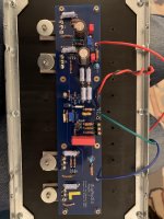
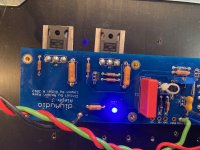
Just powered up my amp. So I can't get 0.35v across the output resistor R18. I only manage 0.186v. And 0.192v on the other board. These are measured when the boards are separately hooked up the the PS.
And the voltage across the output (speaker lines) goes down only to 0.143v for both. No amount of adjusting the pots at R27 and R7 respectively get me further. Any thoughts?
I've had it warm up over 30 min- maybe an hour. And the heat sinks barely warm to touch- maybe a tad above room temp- not sure if it's supposed to be warm with nothing hooked up. In my dim light bulb set up- only a 40w (hard to come by in Cali these days)- it started bright dimmed, then got a little brighter- all quickly. So I'm assuming no catastrophic shorts going on.
The PS is supplying 25.24 v on each side. Image enclosed of one of the amp boards.
TIA,
Attachments
all inputs grounded, no load at output
post ref. sch. and describe how you arranged positions with optional parts choices
post ref. sch. and describe how you arranged positions with optional parts choices
lonepine510, can you also please confirm that the dim bulb tester has been removed
before starting the bias procedure.
before starting the bias procedure.
Oh- no, I had the dim bulb test in series. I'll remove it- always a little nervous to do so...
And, I did not ground the inputs. I take it that's just a jumper between GND and IN- on the both amp boards. Is this needed for the bias adjustment?
I'll try it, removing the dim bulb tester.
Thanks!
And, I did not ground the inputs. I take it that's just a jumper between GND and IN- on the both amp boards. Is this needed for the bias adjustment?
I'll try it, removing the dim bulb tester.
Thanks!
lonepine510, can you also please confirm that the dim bulb tester has been removed
before starting the bias procedure.
Turn your bias back down first; the current could be quite high without it since you've
tried cranking it up. Then remove the dim bulb tester and start the biasing
procedure again.
tried cranking it up. Then remove the dim bulb tester and start the biasing
procedure again.
Last edited:
Hi lonepine510,
with regard to Grounding The Input:
- if you use the amp with single-ended input (non-balanced), IN- should always be connected to GND.
- "Grounding the input" means connecting, during measurement and biasing, IN+ to GND temporarily as well.
Best regards, Claas
with regard to Grounding The Input:
- if you use the amp with single-ended input (non-balanced), IN- should always be connected to GND.
- "Grounding the input" means connecting, during measurement and biasing, IN+ to GND temporarily as well.
Best regards, Claas
I'd replace Q1A, Q1B and Q2 first, WHILST at the same time, making sure the Q7 and Q8 are okay AND they are electrically isolated from the heatsink.
The new JFETs arrived yesterday, so I replaced Q1A and Q1B and the bad channel is now a good channel - working properly, heating up nicely and measuring almost perfectly - bias at 401mV and offset at 0.
Thanks again to you and everyone who chimed in with some ideas on what to check and what to fix. I really appreciate your wisdom and instruction.
I will hook up speakers tonight and spend some time with some music and some whiskey.
Thank you. By removing the dim bulb tester (but not grounding the inputs), I was able to get the measurements- output resistor to 350mV, and outputs to 0 mV offset.
I'll try it again with the inputs fully grounded (for testing, this seems to me simply shorting the inputs to the ground).
A couple follow ups:
1. Now that I've put everything together, I notice a hum from the amp itself. I wonder if I ground the inputs it'll go away?
2. W/o fancy tools (like a 'scope) or sacrificial speakers, is there a way to test if it's safe to hook up? I just don't have any speakers or drivers lying around.
3. Wiring: I know I've raised this before and a number of you have posted some great advice, but I wanted to be clear. I notice that it's hard to keep hook up wire away from the AC lines. Will that cause noise, even if everything is twisted in pairs? Same with the DC lines. Is it worth trying to get the AC mains underneath the bottom? I've seen some beautifully clean and minimalist wiring. but it seems the AC mains are easily managed. See #730.
4. My transformer is mounted vertically. Will rotating it slightly have an effect on noise? I know this is a strategy for horizontally mounted toroids.
Thanks!
Hi lonepine510,
with regard to Grounding The Input:
- if you use the amp with single-ended input (non-balanced), IN- should always be connected to GND.
- "Grounding the input" means connecting, during measurement and biasing, IN+ to GND temporarily as well.
Best regards, Claas
Last edited:
1. Only way to know is to try, and that'll help pinpoint where the hum may be coming from.
2. I'd get a cheap speaker, but that's just me. With no DC offset, the chances of damaging a speaker are pretty small, but it's nice to be on the safe side. Should be less than a few USD for a usable speaker. Can you rob one from anything at all?
3. AC more so than DC. Short answer, yes. Distance is your friend, but you don't need to go to extremes.
4. A bit. I mount mine vertically, and it still has a small effect in my amps.
Pfarrell shared a sequence of lovely tricks somewhere that I just can't seem to find. Search for posts by him, and it may turn up. The best trick I've adopted was using a pair of spare giveaway earbuds to listen for the noise difference while moving wiring and transformers around. It works far better for me than looking at "noise" on a scope, but I am a complete novice when it comes to scope use. It's brilliant in its simplicity. Just hook up the buds to the speaker terminals with and/or without the inputs shorted and go to town with wiggling, twisting, and moving until you reach the lowest noise.
Edited to add: DOH! If you haven't hooked up a speaker yet, then you can ignore #1 for now. It's very likely the transformer humming. Give it a listen.
Last edited:
The new JFETs arrived yesterday, so I replaced Q1A and Q1B and the bad channel is now a good channel - working properly, heating up nicely and measuring almost perfectly - bias at 401mV and offset at 0.
Thanks again to you and everyone who chimed in with some ideas on what to check and what to fix. I really appreciate your wisdom and instruction.
I will hook up speakers tonight and spend some time with some music and some whiskey.
Sweet!!
Great news!
The new JFETs arrived yesterday, so I replaced Q1A and Q1B and the bad channel is now a good channel - working properly, heating up nicely and measuring almost perfectly - bias at 401mV and offset at 0.
Thanks again to you and everyone who chimed in with some ideas on what to check and what to fix. I really appreciate your wisdom and instruction.
I will hook up speakers tonight and spend some time with some music and some whiskey.
Attachments

Aleph J assistance needed
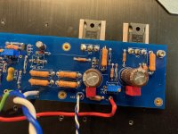
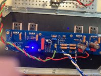
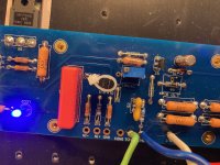
I've been fighting with a faulty board for a while now and could really use some assistance. The power supply and one amp board are up and running as they should, but the second amp board is not working correctly. It powers up (without smoke) and the LEDs light up. However, there is no apparent response from adjusting either trim pot.
In assembling diagnostics I've followed the list provided by Extreme_Boky at post #5753, and as applied by Awajoy at # 5766. Also attached (I hope) are some photos of the faulty PCB.
Any suggestions or observations you may have will be very much appreciated!
Attachments
- Home
- Amplifiers
- Pass Labs
- Aleph J illustrated build guide