Hi, total newb here. I'm learning your electronics language, so forgive me for stating/writing what may be obvious to you.
---
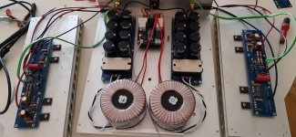
My boards are done.
Primaries and secondaries and bridges done.
My terminal barrier and CL-60s and the little blue cap are done.
Earth ground done.
Back panel done'ish, minus mains wiring.
Assistance needed:
- Trying to figure out what to do with the third CL-60, near the PSU ground, in my 300mm 4U chassis. Which ground? I have almost no room. And what to do with the st_g1 to st_g2? Is it jumpered, too?
- I think the two wires from the IEC connector ("mains," not the switch, which is done) go to the terminal barrier (black, "hot" to the red primary, and white, "neutral" to the black primary), but what wires go to the PSU board on the side closest to the rear panel? I soldered in blade connectors and those screw down Euro connectors bc I wasn't sure which I wanted.
I've been looking at a ton of different completed photos, but it just isn't clear to me or easy to follow. I kinda need some hand holding and I'm a bit ahead of the Noob build thread.
-jason
---
My boards are done.
Primaries and secondaries and bridges done.
My terminal barrier and CL-60s and the little blue cap are done.
Earth ground done.
Back panel done'ish, minus mains wiring.
Assistance needed:
- Trying to figure out what to do with the third CL-60, near the PSU ground, in my 300mm 4U chassis. Which ground? I have almost no room. And what to do with the st_g1 to st_g2? Is it jumpered, too?
- I think the two wires from the IEC connector ("mains," not the switch, which is done) go to the terminal barrier (black, "hot" to the red primary, and white, "neutral" to the black primary), but what wires go to the PSU board on the side closest to the rear panel? I soldered in blade connectors and those screw down Euro connectors bc I wasn't sure which I wanted.
I've been looking at a ton of different completed photos, but it just isn't clear to me or easy to follow. I kinda need some hand holding and I'm a bit ahead of the Noob build thread.
-jason
Help, for some stupid mistake
Hello all from Spain, I'm Miguel and now I'm building an Aleph J pcb.
I have a problem without identify, when I'm adjusting offset, the values of the post are fixed to 23.5v, Seems like the 2K pot of the offset doesn't work and the Q1a and Q1b are hot.....
I hope you can help me....
Hello all from Spain, I'm Miguel and now I'm building an Aleph J pcb.
I have a problem without identify, when I'm adjusting offset, the values of the post are fixed to 23.5v, Seems like the 2K pot of the offset doesn't work and the Q1a and Q1b are hot.....
I hope you can help me....
Attachments
Last edited:
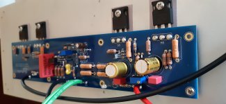
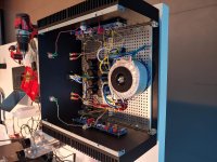
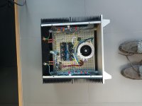
Adding more photos
Thanks again Dennis.
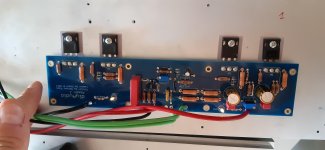
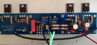
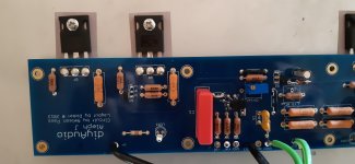
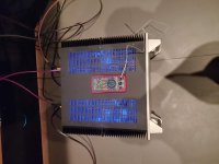
I atach more pictures.
Is a amp chasis bought for other amp. But current of transformer are 18-0-18 and 25v on the PSU.
Thanks again Dennis.
I atach more pictures.
Is a amp chasis bought for other amp. But current of transformer are 18-0-18 and 25v on the PSU.
Attachments
-
 16034602042066473010950080619030.jpg777.8 KB · Views: 287
 -
 16034603051654878229340128890669.jpg690.6 KB · Views: 277
 -
 16034603265156913315236150198364.jpg792.3 KB · Views: 285
 -
 16034603446505205652332380128563.jpg967.4 KB · Views: 290
 -
 16034603603315017171999622125621.jpg818.8 KB · Views: 175
 -
 16034603802139124941218159745001.jpg705.3 KB · Views: 138
Last edited:
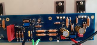
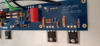
What part are you using for Q2? Double check pin out vs. CBE on the pcb. What is the voltage over R7?
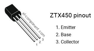
Edit: I think Q2 may be installed the wrong way. With ZTX parts you have to look at the flat side for identifying the pins. The print is on the side with the rounded corners if I'm not mistaken, easy to get the pin out wrong. Check the other small transistors too!
Edit: I think Q2 may be installed the wrong way. With ZTX parts you have to look at the flat side for identifying the pins. The print is on the side with the rounded corners if I'm not mistaken, easy to get the pin out wrong. Check the other small transistors too!
Last edited:
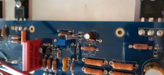
Q2 is supposed to be the P-channel ZTX550.
You have a 450 installed. 🙂
It is also in backwards, the ZTX pinout is EBC.
EDIT: Also, it means you probably have a wrong transistor in either the Q3 or Q4 position, and looking at the photos, they also appear installed backwards.
You have a 450 installed. 🙂
It is also in backwards, the ZTX pinout is EBC.
EDIT: Also, it means you probably have a wrong transistor in either the Q3 or Q4 position, and looking at the photos, they also appear installed backwards.
Last edited:
Thank you very much !!! I'm going to remove and mount again !! Let's see whats happen...
Thanks again.
Thanks again.

Yes, still working perfect, 50 degres with 5 kg of heatsink.
Good with 12ax7 preamp.
Thanks for all !!
Good with 12ax7 preamp.
Thanks for all !!
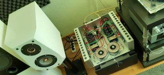
Hi all,
I thought I would post some pics of my recently completed Aleph J. I have to say it is the finest amplifier I have heard in my system. Right now it is being fed directly from my Project DAC but I am awaiting a Korg B1. It powers my Dynaudio Contour LE 3.4s just fine even though they are not particularly efficient.
I thought I would post some pics of my recently completed Aleph J. I have to say it is the finest amplifier I have heard in my system. Right now it is being fed directly from my Project DAC but I am awaiting a Korg B1. It powers my Dynaudio Contour LE 3.4s just fine even though they are not particularly efficient.
Attachments
Nice job! I agree that this is a very fine amp. You’ll like the B1 Korg NuTube preamp. Make sure you that you properly dampen the Korg NuTube to eliminate microphony.
Dear all, I've problems with this amp I've just assembled. All settings have been done (R7 and R27) but the amp has a very high distortion and volume is low. Moreover, all Mosfet are cold, and they start heating only if I increase the offset to values higher than 0,4 V. Power supply is ok (+ and - 27 V). What's wrong? Thanks for your help.
I would start from checking if all resistors have correct values.
If something like brown Dales it would be quick check, if stripes values then less quick.
If something like brown Dales it would be quick check, if stripes values then less quick.
Thanks for the answer. All resistors have been checked before mounting...everything is cold..
Can you take a photo for checking probably visual errors?
Also check Q2, Q3, Q4, for pinout.
BC have CBE pinout and ZTX are EBC.
Also check Q2, Q3, Q4, for pinout.
BC have CBE pinout and ZTX are EBC.
- Home
- Amplifiers
- Pass Labs
- Aleph J illustrated build guide