I use DAC as a source, with 33ohm I/V resistors loading the Aleph J input (which is very wide band, very high input impedance). DAC loves it; it really shines with such a high input impedance load🙂. However, Aleph J, having these input characteristics, and NO volume pot at its input, could cause some issues if the source (pre-map) output impedance is high, or if there are interconnects' issues - hence my suggestion to load Aleph J input with a potentiometer.
Before you start changing the topology of your pre-amp, short the RCA hot pin to ground and tell us what happens...? Is that white, broad-spectrum noise still there?
In general, it is a good idea to have a volume pot after the pre-amp / before the output amp because you can attenuate any noise that the pre-amp creates…
Okay, thanks! I'll try shorting the RCA hot pin tonight and report back.
Extreme_Boky, your hunch was spot on. I just tried shorting the RCA hot pin to ground and the white broad-spectrum noise disappeared.
Any reason why I couldn't just add a wire to make the short semi-permanent? Assuming that's not the best solution, how do you recommend loading the Aleph J input with a pot? I'd prefer not to rewire the BA3FE if I can avoid it, and am open to adding a second volume pot to the chain. Is there such a thing as a standalone volume pot that you can wire up external to a chassis? I'm a newbie at all of this, so thanks for your help with these questions!
Any reason why I couldn't just add a wire to make the short semi-permanent? Assuming that's not the best solution, how do you recommend loading the Aleph J input with a pot? I'd prefer not to rewire the BA3FE if I can avoid it, and am open to adding a second volume pot to the chain. Is there such a thing as a standalone volume pot that you can wire up external to a chassis? I'm a newbie at all of this, so thanks for your help with these questions!
Do you hear that white noise when your Alep J is not connected to anything, i.e. no interconnects plugged in RCA's?
With only speakers connected and nothing plugged in RCA's, the white noise shouldn't be audible. If it IS, please post detailed photos of the input wiring and PCB's.
If Alep J is quiet, then re-wire the pre-amp potentiometer; move it from input to output - this is very straightforward and it shouldn't take long at all.
Last edited:
In general, it is a good idea to have a volume pot after the pre-amp / before the output amp because you can attenuate any noise that the pre-amp creates…
If you don’t mind a variable output impedance and a loss of about 3db.
The variable impedance, introduced by a potentiometer, will affect the pre-amp input stage, or the output amplifier input stage... unless the pre-amp has a special stage that specifically caters for the potentiometer at its input🙂
It all depends on topologies and varies widely from case-to-case.
I personally like to place the potentiometer at the pre-amp output stage, because this attenuates the noise as well; if the potentiometer is placed at the pre-amp input, then the residual noise of the pre-amp output stage will be amplified by a full gain of the output amplifier.
There are pros and cons… I use JRiver to attenuate the sound; no potentiometers of any kind. Again, there are pros and cons to this approach as well…, but in MY case, with only 33ohms of DAC output impedance, my approach has more pros than cons.
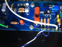
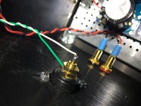
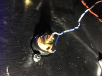
Well, the white noise was still there when I unplugged the RCA interconnects. It is faint, but still audible. Here are some photos of the input wiring. Thoughts?
[Sorry if the images are displaying upside down. Not sure why that's happening...]
[Sorry if the images are displaying upside down. Not sure why that's happening...]
Attachments
Are you able to test with the inputs shorted? (You can make a cheap shorting
plug from a junk RCA cable by just shorting the signal and ground together)
plug from a junk RCA cable by just shorting the signal and ground together)
Well, the white noise was still there when I unplugged the RCA interconnects. It is faint, but still audible. Here are some photos of the input wiring. Thoughts?
[Sorry if the images are displaying upside down. Not sure why that's happening...]
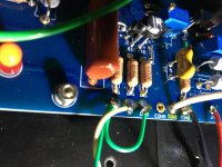
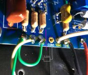
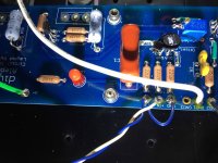
Your soldering is good. Just do the Extreme_Boky's hum elimination mod, as per attached photo. The pink line is where you should cut the PCB track underneath the PCB board. I used the 10ohm / 5W resistor without back-to-back diodes.
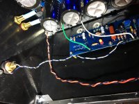
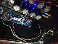
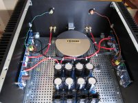
The second photo I attached will show you how to position the input wiring -> it should NOT run in parallel with the speaker wiring, but as close as possible to the chassis and/or heatsink.
Once you're done, and you mount/connect everything back together, MAKE SURE there's no conductivity between MOSFET's pins and the chassis.
Attachments
Last edited:
Originally Posted by Extreme_Boky View Post
In general, it is a good idea to have a volume pot after the pre-amp / before the output amp because you can attenuate any noise that the pre-amp creates…
i do this all the time, my reason is that i wanted to be able to connect a cd player or a smartphone directly to the amplifier...
i do this all the time, my reason is that i wanted to be able to connect a cd player or a smartphone directly to the amplifier...
ok , handy if you want or must have that option of so called "passive preamp"
but , in case when you connect decent proper preamp , having attenuator in between is negating absolutely everything what preamp in case is bringing to the game
same as applying hand-brake , while jumping on the throttle , driving straight .....
a line preamp cap coupled will have a 100k to 1 meg resistor to keep the output side of the coupling cap to zero volts or ground, so what is a 20k to 100k pot at the input of the power amp going to add? not much...
when using a proper preamp, you can set the input pot to maximum anyway and if you wanted to balance channels of your power amp to suit local installation conditions then you have this option...
a line amp will have a 1k output impedance anyway....
when using a proper preamp, you can set the input pot to maximum anyway and if you wanted to balance channels of your power amp to suit local installation conditions then you have this option...
a line amp will have a 1k output impedance anyway....
Last edited:
same as applying hand-brake , while jumping on the throttle , driving straight .....
 Now, why would you be doing that?? Must stop, immediately!
a line preamp cap coupled will have a 100k to 1 meg resistor to keep the output side of the coupling cap to zero volts or ground, so what is a 20k to 100k pot at the input of the power amp going to add? not much...
when using a proper preamp, you can set the input pot to maximum anyway and if you wanted to balance channels of your power amp to suit local installation conditions then you have this option...
a line amp will have a 1k output impedance anyway....
well , your mileage may and must vary from mine .....
I spent considerable amount of time and energy to get rid even of any kind of resistive attenuator in signal chain, so that is my experience
if you don't hear difference, even better for you , especially for your wallet
well , your mileage may and must vary from mine .....
I spent considerable amount of time and energy to get rid even of any kind of resistive attenuator in signal chain, so that is my experience
if you don't hear difference, even better for you , especially for your wallet
your choice, there is a difference though, i am able to tame hum that way so i was happily surprised to read extreme_boky replied based on the exact same experience as me...
volume pots do not cost much so i use them..
Are you able to test with the inputs shorted? (You can make a cheap shorting
plug from a junk RCA cable by just shorting the signal and ground together)
Thanks, Dennis. I hadn't tried shorting the inputs yet. Just did and it virtually eliminated the noise.
Your soldering is good. Just do the Extreme_Boky's hum elimination mod, as per attached photo. The pink line is where you should cut the PCB track underneath the PCB board. I used the 10ohm / 5W resistor without back-to-back diodes.
The second photo I attached will show you how to position the input wiring -> it should NOT run in parallel with the speaker wiring, but as close as possible to the chassis and/or heatsink.
Once you're done, and you mount/connect everything back together, MAKE SURE there's no conductivity between MOSFET's pins and the chassis.
Thanks for these suggestions, Extreme_Boky. I'll give them a try.
Also, in the course of testing by unplugging and the replugging the RCA interconnects, a lower frequency hum developed in the right channel. It wasn't there initially, but now it's there if I have the RCA interconnect plugged in. Any suggestions for diagnosing that issue, or is it likely related to the higher frequency white noise?
It sounds like a bad connection. Have you tried poking around inside with a plastic stick? I know it sounds crude, but it sure beats sticking your hands inside to wiggle wires.
The pink line is where you should cut the PCB track underneath the PCB board. I used the 10ohm / 5W resistor without back-to-back diodes.
Hi EB,
Why would it be required to use a 5W R in this position, just so I understand? I have already put in a 1/4W 10R on the back side of the board. Not sure what currents would be in the input ground?
Thanks
Just in case of a fault current needing to go through that resistor.... you probably recall that others use a "back-to-back" diodes, to ensure the fault current would flow irrespective of which potential is the fault current sitting at, referenced to chassis. But, in whole honesty, I am thinking now that it is maybe better to use a smaller power fusible resistor, that will OPEN / BLOW in case there's a fault, which will ISOLATE the fault condition.
All Zen amplifier pdf schematics have a 40A bridge in place of a CL-60.
I suppose, once you understand the pros and cons of each approach, it is only YOU who could decide what best suits your needs/meets your expectations/address your concerns.
There's always a possibility to place the V+ and V- fast-blow fuses on a DC side.
Different people perceive hazard in a different way; they also assign the severity of the risks, associated with those hazards, in a different way, and use different approaches to mitigate the risk. Furthermore, the resulting (mitigated or reduced) risk might be satisfactory for a person A, but NOT for a person B...
Last edited:
- Home
- Amplifiers
- Pass Labs
- Aleph J illustrated build guide