Getting near the end of my Aleph J project, it’s my first amplifier and has been a great learning experience, thanks everyone for all of your posts! Question on wiring both balanced and rca inputs in single chassis. I have some 6 conductor wire that is shielded and sports an uninsulated ground wire. I was going to run one wire each from +v rca and xlr terminating each to +v input on board, same with -v . Now I’m not sure if I should use the bare shield wire connected to the ground on the xlr and terminate on the chassis or use one of the other insulated wires in the package. From my reading here grounding is very important with respect to noise elimination, perhaps I should keep it simple and just use some standard wire. Does anyone see an advantage to the insulated cable?
I'm a noob to all this but I wouldn't ground that wire to the chassis. I think the XLR should be grounded to the board and such there should be only one grounded spot on the base plate that has the Cl60. I grounded mine on the board and its dead silent. In any event the masters will correct us both.....
Last edited:
I'm inclined to do as you've done Blk Dynamite, dead silent works for me.I'm a noob to all this but I wouldn't ground that wire to the chassis. I think the XLR should be grounded to the board and such there should be only one grounded spot on the base plate that has the Cl60. I grounded mine on the board and its dead silent. In any event the masters will correct us both.....

Hi
I just started to build the Aleph J. Right now i work on the psu.
I have a question. I am shure it is answered in this tread. But i was lacy and hope someone would answer here so i dont have to search the whole tread 🙂
with 2*18vac inn to the psu. What should i measure between v+v- and between gnd v+ and v- I really hope someone can answer me 🙂 🙂
With a measured 18VAC on your transformer secondary and a suitable PSU with no load and capacitance value as required for a class A amp, you will measure +25VDC to ground and -25VDC to ground. If your incoming AC mains supply voltage to the transformer primary winding is high, then you might read up to 27VDC unloaded on the PSU. This voltage will drop under load and depending on the transformer regulation percentage ratio and the VA rating of the transformer.
With a measured 18VAC on your transformer secondary and a suitable PSU with no load and capacitance value as required for a class A amp, you will measure +25VDC to ground and -25VDC to ground. If your incoming AC mains supply voltage to the transformer primary winding is high, then you might read up to 27VDC unloaded on the PSU. This voltage will drop under load and depending on the transformer regulation percentage ratio and the VA rating of the transformer.
Thank you for reply. So it is near correct when i measure 24vdc from v+ and v- to gnd and i measure 48vdc between v+ and v- then 🙂
Thank you for reply. So it is near correct when i measure 24vdc from v+ and v- to gnd and i measure 48vdc between v+ and v- then 🙂
Correct
Correct
Good. Then i know the psu is working as it should. And i can continue with the build 🙂 Thanks to gary s and Earthquake for helping me whit this question 🙂
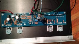
I'm trying to finish up my first build and have run into a problem. Everything is assembled and I am measuring +25.5 dcv and +25.5 dcv leaving the PCU. I am not able to get the Mosfets on either the right or left channel to heat up.
The source resistors are measuring 0v . the voltage across R8 is around 8.43 volts, I'm assuming that since the voltage to the amp board is ok, that is where the problem lies. It also then appears that I made the same mistake on each amp board but I can't figure out what that was. I am new to this and can't figure out the schematic enough to figure out where to start looking.😕
I've attached a poor photo and will take some better ones later if needed.
Attachments
I'm trying to finish up my first build and have run into a problem. Everything is assembled and I am measuring +25.5 dcv and +25.5 dcv leaving the PCU. I am not able to get the Mosfets on either the right or left channel to heat up.
The source resistors are measuring 0v . the voltage across R8 is around 8.43 volts, I'm assuming that since the voltage to the amp board is ok, that is where the problem lies. It also then appears that I made the same mistake on each amp board but I can't figure out what that was. I am new to this and can't figure out the schematic enough to figure out where to start looking.😕
I've attached a poor photo and will take some better ones later if needed.
Have you pre-set the bias pot as per the build guide? Also, what value resistor is that for R8? Should be 1kohm, looks like 100 from pic. A few of the solder joints look like they should be redone.
Have you pre-set the bias pot as per the build guide? Also, what value resistor is that for R8? Should be 1kohm, looks like 100 from pic. A few of the solder joints look like they should be redone.
I just noticed I installed both pots in the wrong spot.😡
I just noticed I installed both pots in the wrong spot.😡
Glad that you found it! Hopefully you’ll have it up and running soon.
Glad that you found it! Hopefully you’ll have it up and running soon.
Thanks. Got everything up and running yesterday. No hum and it sounds great!
Thanks. Got everything up and running yesterday. No hum and it sounds great!
Fantastic. Congratulations!
Hi
I have another question regarding Aleph J
Can i use a heatsink that is 6,6 inch high and 15,7 inch long
Or do it have to be bigger due to the heat it develop
I have another question regarding Aleph J
Can i use a heatsink that is 6,6 inch high and 15,7 inch long
Or do it have to be bigger due to the heat it develop
That heatsink is a common size - 4U x 400mm.
Do you have one or two? For one channel that heatsink will be very good. For two channels it's going to be small.
Do you have one or two? For one channel that heatsink will be very good. For two channels it's going to be small.
That heatsink is a common size - 4U x 400mm.
Do you have one or two? For one channel that heatsink will be very good. For two channels it's going to be small.
I have two of them. So it is for one channel. I am very glad i can use them. So my Aleph J fits in my rack 🙂
- Home
- Amplifiers
- Pass Labs
- Aleph J illustrated build guide