use pair of IRFP150 , crank them to your liking
that's practically pair of IRFP240 in one case
so , no matching needed
for more info , look in (newer) Babelfish J thread
aha , yes - halve value of all 3W resistors , for that ........ 0R27 is OK
that's practically pair of IRFP240 in one case
so , no matching needed
for more info , look in (newer) Babelfish J thread
aha , yes - halve value of all 3W resistors , for that ........ 0R27 is OK
I can only second what Zen Mod said.
That case combined with the lower voltage should give you the option to run much higher bias current, which is a good recipe for best sound ...
In a case comparable to your 4U/400 I have run a single pair of IRFP140 at +/- 19V and 2.2 Amp bias current. 😉 Source resistors are 0.22 Ohms.
Best regards, Claas
Thank you Claas,
I take it the .47R output resistors in parallel stay the same and dont change even with the source resistor change?
Regards,
Matt
I take it the .47R output resistors in parallel stay the same and dont change even with the source resistor change?
Regards,
Matt
nope
as I said - you need to change values of all
point me to your exact schematic , and I'll write them by nomenclature
as I said - you need to change values of all
point me to your exact schematic , and I'll write them by nomenclature
Hi ZM,
Sorry for my stupidity, when reading your Babelfish J thread, I see likely two .27R 3w resistors as output resistors if a single vertical pair of IRF120 with .27R source resistors are used.
Here is the schematic I will be following, it is the one from the most recent DIYstore Aleph J boards.
Sorry for my stupidity, when reading your Babelfish J thread, I see likely two .27R 3w resistors as output resistors if a single vertical pair of IRF120 with .27R source resistors are used.
Here is the schematic I will be following, it is the one from the most recent DIYstore Aleph J boards.
Attachments
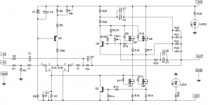
whatever you do , R16,7,18,19,20,21,22,23 ...... are all of same value
of course that last group (sense group on output ) can be made of different number of resistors with different value (say , to have just 2pcs , not zillion ) , but group value must stay the same
practically - as many source resistors you have in output (counting up and down) , same number is in sense group
Yes,
in my single output pair Aleph (like Aleph Mini), I have 0R22 for each source resistor and 0R11 as sense group total 🙂
Best regards, Claas
in my single output pair Aleph (like Aleph Mini), I have 0R22 for each source resistor and 0R11 as sense group total 🙂
Best regards, Claas
I have a 4U 400mm Dissipante chassis with stout dual mono +18v/-18v rails, and want to try it with a low voltage Aleph J build.
I have very efficient speakers and am not worried about maximum power output, but rather, how to get potentially the best sound out of the lower rail voltage.
Is it best to use all 4 output mosfets, or drop to one pair of outputs, ala Mini Aleph-J?
Thanks,
Matt
Can you have that 4U 400mm Dissipate chassis with UMS heatsinks? I like the 400mm depth and 40mm heatsinks, but I don't think you can get 2 X 200mm heatsinks (per each side) with "UMS" pre-drilled holes..??
Can you have that 4U 400mm Dissipate chassis with UMS heatsinks? I like the 400mm depth and 40mm heatsinks, but I don't think you can get 2 X 200mm heatsinks (per each side) with "UMS" pre-drilled holes..??
Anyone?
Anyone?
what I'm seeing in UMS pdf , I understand as UMS is made for both 300 deep and 400 deep
excluding one central hole , no reason why 400 deep can't be made from two pieces ..... however exact deal/arrangement can confirm only someone from DiyA/Store team
ask them in Store related threads
excluding one central hole , no reason why 400 deep can't be made from two pieces ..... however exact deal/arrangement can confirm only someone from DiyA/Store team
ask them in Store related threads
Is it really necessary to hava 4 Units height or is a 3H 400mm Chassis also OK for a two channel Aleph J?
I love the smaller width of the Mini Dissipantes. The space inside for the power supply is more than enough in there.
Plannes is to use Kapton Isolators for the FETs which should Keep them cooler and eventually a thick copper "heatspreader under them.
Regards
Dieter
I love the smaller width of the Mini Dissipantes. The space inside for the power supply is more than enough in there.
Plannes is to use Kapton Isolators for the FETs which should Keep them cooler and eventually a thick copper "heatspreader under them.
Regards
Dieter
you can squeeze it even in 2U/300 
then fans are your only option
for 3U/400 ..... summer in Europe - Babysitter is a must
then fans are your only option
for 3U/400 ..... summer in Europe - Babysitter is a must
If you again have the same summer temperatures you had this past summer in Europe, my suggestion is, no.
Biggest enemy to heatsink doing a good job is ambient temperature.
Biggest enemy to heatsink doing a good job is ambient temperature.
Thanks for your replies.
That's true, it was a hot summer, but I loved it.
It will not be the only amp here. If it's too hot I can use a Hypex class-D amp instead. 🙂
Regards
Dieter
That's true, it was a hot summer, but I loved it.
It will not be the only amp here. If it's too hot I can use a Hypex class-D amp instead. 🙂
Regards
Dieter
Another AJ Build
Over the summer I did an Amp Camp Amp build. I was, and am, totally floored by its beautiful, clean sound. So, I started reading more on diyaudio... This eventually led to a visit with 6L6, and you all know where that led!
Thanks to inspiration, lots of sage advice, and a few parts from 6L6, this weekend I've made good progress on my first substantial Pass-inspired build. The last 2 weeks was ordering the chassis, the AJ PCB, and BOM for the universal PSU and AJ. Everything came in this week, so I started in... I made some mistakes and will still some assistance in fixing a few things, but I wanted to post it as it happened, the good, the bad, and the fugly.

My PSU boards (from 6L6) were split, so I started by completing the attachment points for these and to the diode boards (more on this later).

Realized, via 6L6 again, that PSU will probably need to have diode boards split off to fit the Deluxe 4U chassis.

Parts for the PSU sorted and each tested.


AJ board stuffed with resistors.

Capacitors

JFET's in (I have one board's Q2 reversed, still have to fix that!)

Completed AJ boards (minus the MOSFET's and still with one reversed Q2)

About ready to start some assembly.
I know I still have a long way to go, but want to post progress.
Thanks to all the contributors to this thread (yes, I read the whole thing over the last month), to the diyaudio store crew, to NP for sharing this design and details, and especially to 6L6 who continues to guide me in this build and lead me into Class A enlightenment.
Greg
Golden, CO
Over the summer I did an Amp Camp Amp build. I was, and am, totally floored by its beautiful, clean sound. So, I started reading more on diyaudio... This eventually led to a visit with 6L6, and you all know where that led!
Thanks to inspiration, lots of sage advice, and a few parts from 6L6, this weekend I've made good progress on my first substantial Pass-inspired build. The last 2 weeks was ordering the chassis, the AJ PCB, and BOM for the universal PSU and AJ. Everything came in this week, so I started in... I made some mistakes and will still some assistance in fixing a few things, but I wanted to post it as it happened, the good, the bad, and the fugly.
My PSU boards (from 6L6) were split, so I started by completing the attachment points for these and to the diode boards (more on this later).
Realized, via 6L6 again, that PSU will probably need to have diode boards split off to fit the Deluxe 4U chassis.
Parts for the PSU sorted and each tested.
AJ board stuffed with resistors.
Capacitors
JFET's in (I have one board's Q2 reversed, still have to fix that!)
Completed AJ boards (minus the MOSFET's and still with one reversed Q2)
About ready to start some assembly.
I know I still have a long way to go, but want to post progress.
Thanks to all the contributors to this thread (yes, I read the whole thing over the last month), to the diyaudio store crew, to NP for sharing this design and details, and especially to 6L6 who continues to guide me in this build and lead me into Class A enlightenment.
Greg
Golden, CO
The PSU, minus the rectifier boards, may also be mounted on the inside of the front panel. The mounting holes on the PCB line up with M3 threaded holes in the front panel.
Looks great. I’m hoping to get started soon too, just waiting for the JFETs and PCB’s to be back in stock. 🙁
Following up on progress to post #757 above...
Spent 6 hrs at Jim's house today working at his bench with expert guidance. He is SO patient!
He showed me how to use his desoldering gun and split off the diode boards.
Once split, we then used this excellent and amazing test jig called Quasimodo to measure for the transformer snubber components (RS1, CS2, and CX2 on the diyAudio UPS v3 PCB). All I know is that replaces some advanced mathematics that I did not understand in the least. Jim also made a quick call to Mark Johnson, designer of the above test-jig, to confirm a few details about our testing.
Jim pointed out a few soldering touch ups on the AJ boards which we fixed. I finished up some soldering on the PSU's and then got to work on layout and mounting.
Wiring up the PSU followed. Once all internal connections were made, a light bulb tester connected it to mains voltage. With a cardboard box protecting us from possible fireworks, I flipped the power switch. The bulb, as desired, lit briefly and then dimmed. No blue smoke or burning odors were detected. Rails measured -25/+25 V DC as hoped. Success with the power supply!!
It was a great day with great company and some nice jazz quartet standards streaming through paired ACA's. Here are some build photos for now because it will be a couple of weeks before I get more time with this project.
- Home
- Amplifiers
- Pass Labs
- Aleph J for Universal Mounting Spec