I can now drill and tap M3, M4 and M5 holes with my eyes closed.
It is a very useful skill. I had tapped plenty of thru-holes over the years but for this build I wanted to tap the heat sinks the way the manufacturer does it. Now I know how to tap blind holes also.
Oh, I completely forgot to mention;
PCB Update
The changes that were suggested by grimberg and buzzforb (a couple of drill size problems, as well as a de-cluttered silkscreen) have been made, and those files are in the hands of people to send them out for production. I have no idea at all regarding timeline as to when they will be available in the store, but the ball is rolling.
Oh, I completely forgot to mention;
PCB Update
The changes that were suggested by grimberg and buzzforb (a couple of drill size problems, as well as a de-cluttered silkscreen) have been made, and those files are in the hands of people to send them out for production. I have no idea at all regarding timeline as to when they will be available in the store, but the ball is rolling.
Thanks, looking forward to it!
Oh, I completely forgot to mention;
PCB Update
The changes that were suggested by grimberg and buzzforb (a couple of drill size problems, as well as a de-cluttered silkscreen) have been made, and those files are in the hands of people to send them out for production. I have no idea at all regarding timeline as to when they will be available in the store, but the ball is rolling.
Who would I need to bribe to ask for a black PCB?
 😎
😎Oh, I completely forgot to mention;
PCB Update
The changes that were suggested by grimberg and buzzforb (a couple of drill size problems, as well as a de-cluttered silkscreen) have been made, and those files are in the hands of people to send them out for production. I have no idea at all regarding timeline as to when they will be available in the store, but the ball is rolling.
Any feedback yet?
BTW I see you have made good progress on your F5T.
No feedback on PCBs yet -- Jason's been sick and working on the ACA.
I'm building my Aleph J currently, something's out of whack and I haven't figured it out yet... but it's only been together a day or so.
F5T progress? Lol... It is waiting until the AJ is complete and properly photographed etc... then it will go into the big chassis. (I can use the PSU from the F4 easily for the AJ, whereas everything for the F5T must be changed.)
Thanks. It's only a hobby, so don't overdo it.
I should have done my F5T on Teabag's boards first. Well, the boards are populated, but I don't have the bigger PSU. I am waiting for Antek to get some 24V trafos in stock. Must be you guys that keep on depleting their stock.😉
I should have done my F5T on Teabag's boards first. Well, the boards are populated, but I don't have the bigger PSU. I am waiting for Antek to get some 24V trafos in stock. Must be you guys that keep on depleting their stock.😉
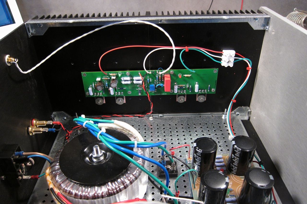
I have my Aleph J boards populated, biased and working properly in the big DIYaudio chassis. I have a huge input ground loop, but that is an issue with my wiring rather than the boards. The channels are nice and quiet when played alone or with the inputs shorted.
I have my Aleph J boards populated, biased and working properly in the big DIYaudio chassis. I have a huge input ground loop, but that is an issue with my wiring rather than the boards. The channels are nice and quiet when played alone or with the inputs shorted.
How 'bout some photos?
I cant really see anything unusual. Ill have to look at ground plane on boards, but it doesnt seem likely. You said there was no issue on the F4 using same configuration in chassis?
You said there was no issue on the F4 using same configuration in chassis?
No problem at all. That's what's stumping me...
Last edited:
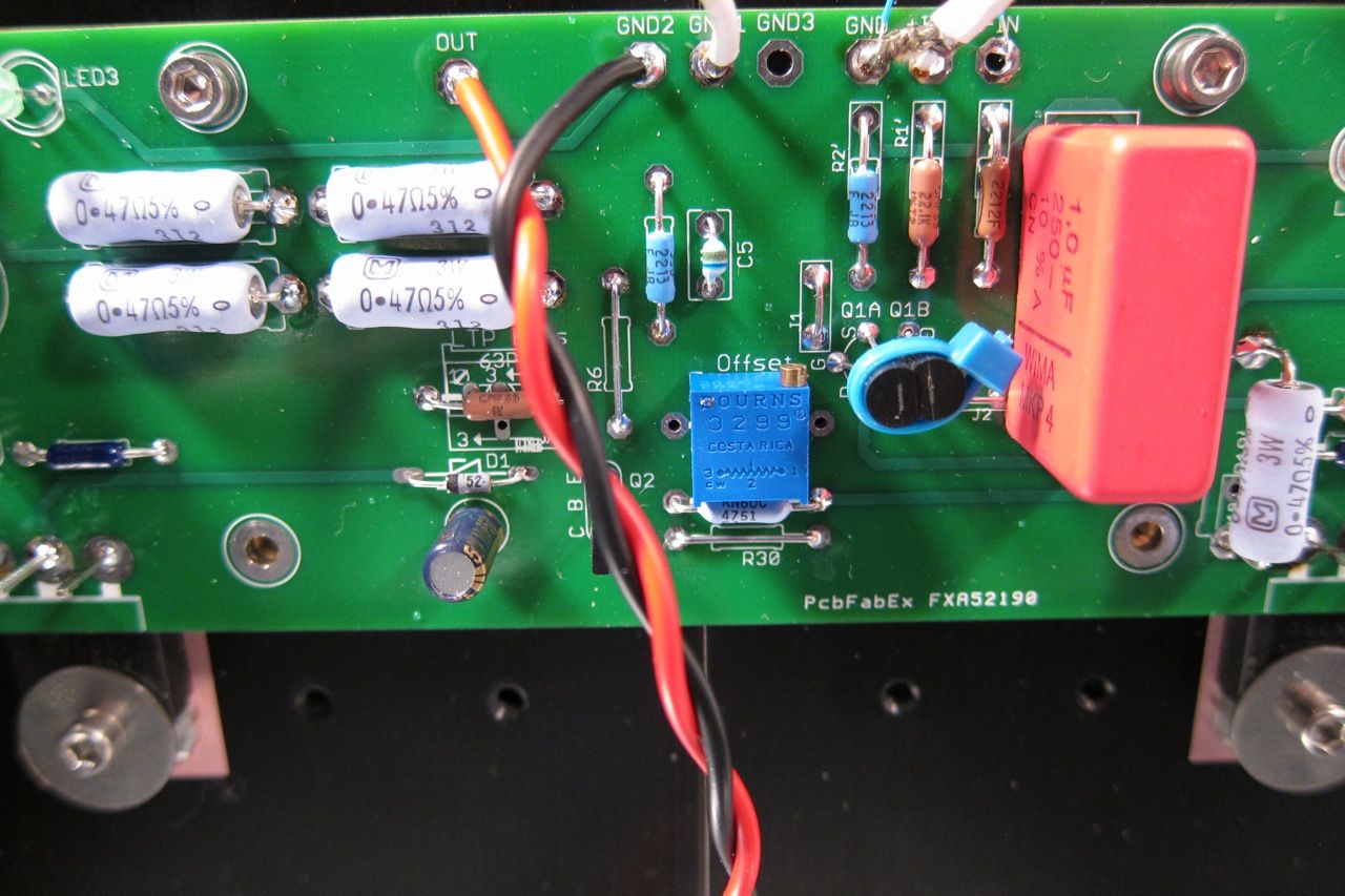
My first gues is small connector wire tying (-) input to ground. A major difference in the topology of the F4 and AJ is the FE. F4 is SE and AJ is balanced capable. If you know the F4 is dead silent in same case and same configuration, then I would be looking at the innput first. That little wire seems easy to pick on. I would have suggested transformer and PSU size for an amp that draws almost 10A current total, but i am less inclined to think so and the fac that it is quite with input grounded suggest it is a non issue. THe PCB has signal and output ground coming fromsame point, so i dont think it is a layout issue. Try replacingthe wire(mine is done same exact way, but heavier wire) and see what happens.
Did you watch the output when you hooked up RCA to make sure no oscillations were triggered?
Did you watch the output when you hooked up RCA to make sure no oscillations were triggered?
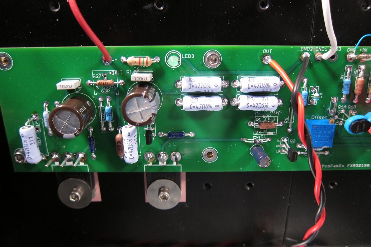
Those multiple GND connections on the PCB; is that functioning as the audio (star) ground? I would not have done it that way. Also, the cable for the power ground to the PCB seems very long. Don't know if that can cause problems, but would have tried to keep that power ground as short as possible.
Edit: On second thought I don't think it is the problem though. The fact that I would not do it does not negate the fact that your scheme seems technically correct. If the hum is gone with the input shorted then by process of elimination the hum must be caused by a problem on the input circuit grounding. Just as an experiment; what happens if you disconnect the signal ground on only one if the input connections?
Edit: On second thought I don't think it is the problem though. The fact that I would not do it does not negate the fact that your scheme seems technically correct. If the hum is gone with the input shorted then by process of elimination the hum must be caused by a problem on the input circuit grounding. Just as an experiment; what happens if you disconnect the signal ground on only one if the input connections?
Last edited:
Sorta of a tree star. It doesn't have to be a single star point to work. Only way to better it is to have all ground connections going to PSU PCB. Starts to get hairy with wiring that way unless whole amp is designed for it. Ideal grounding scheme can be seen in XA 30.5 review at six moons. Nelson has it all on one sub board. this is how i will be doing it in my clone.
My first gues is small connector wire tying (-) input to ground.
Well if you look at Nelson's amps with balanced inputs, he uses a balanced audio line from the rear panel to the circuit board, and then for unbalanced operation just sticks a jumper in the XLR connector. I imagine the resistance of that arrangement would be more than the short length of small-gauge jumper wire that 6L6 has used?
Just as an experiment; what happens if you disconnect the signal ground on only one if the input connections?
It's actually louder... the loop problem from the inputs is being carried on the signal + more than the ground. As the RCA plugs are being inserted they are really loud when the grounds are not touching, and get a little quieter once the grounds contact.
One input by itself is hummy, two sounds like an angry hornet, and inputs shorted is quiet.
Also, I tried a bigger piece of wire connecting -in to gnd, with no difference.
- Home
- Amplifiers
- Pass Labs
- Aleph J for Universal Mounting Spec