try like this :
twisted triple of wires ( +,-,gnd) from PSU to (each) output pcb , shortest possible route , not going from coast to coast);
RCAs isolated from chassis ; their GND tabs connected with one wire bridge ; from exact mid point of that bridge - one wire to main GND point of PSU ( which ic connected to chassis/safety gnd via NTC)
then shielded ( or twisted pair ) from each RCA to correspondent channel pcb , where gnd (shield ) wire connected just on RCA side
if needed - fat , shortest possible , wire as bridge connecting two pcbs main GND points
Last edited:
Well if you look at Nelson's amps with balanced inputs, he uses a balanced audio line from the rear panel to the circuit board, and then for unbalanced operation just sticks a jumper in the XLR connector. I imagine the resistance of that arrangement would be more than the short length of small-gauge jumper wire that 6L6 has used?
I know, just suggesting a possible issue. Hook scope up to it with inputs grounded and then plug in amp. Lets see what's happening
Attachments
try like this :
twisted triple of wires ( +,-,gnd) from PSU to (each) output pcb , shortest possible route , not going from coast to coast);
RCAs isolated from chassis ; their GND tabs connected with one wire bridge ; from exact mid point of that bridge - one wire to main GND point of PSU ( which ic connected to chassis/safety gnd via NTC)
then shielded ( or twisted pair ) from each RCA to correspondent channel pcb , where gnd (shield ) wire connected just on RCA side
if needed - fat , shortest possible , wire as bridge connecting two pcbs main GND points
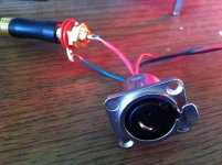
Yes Choky. My assumption was that his RCA's are isolated completely from the chassis. If not, it may cause some major problems, but I am sure he knows better. 😀
twisted triple of wires ( +,-,gnd) from PSU to (each) output pcb , shortest possible route , not going from coast to coast)
Ok, I was going to try that next anyway...
They already are, so that's easy! 🙂RCAs isolated from chassis
Ok, I like it! Is this different from equal length wires connecting to same point on PSU?their GND tabs connected with one wire bridge ; from exact mid point of that bridge - one wire to main GND point of PSU
Yep.(which is connected to chassis/safety gnd via NTC)
So the shield will be at same potential as GND... Very good!! 😀then shielded ( or twisted pair ) from each RCA to correspondent channel pcb , where gnd (shield ) wire connected just on RCA side
Will try that last to see if it helps.if needed - fat , shortest possible , wire as bridge connecting two pcbs main GND points
Not sure what's going on there with your hum situation, will be interesting to see what finally solves that. Looking at those pics, just wanted to make an observation. In building that amp, I would have swapped positions of the power transformer and the PS board. The way the Firstwatt (and many others) are done.
just wanted to make an observation. In building that amp, I would have swapped positions of the power transformer and the PS board.
Sounds interesting... Why?
Is there any connection that could be made shorter that way? I'm asking because a second set of eyes is always helpful and maybe you are seeing something I'm not... 🙂 🙂 🙂
I bet you a beer that it's done that way to get the balance of the amp in the center of the chassis more than anything else...The way the Firstwatt (and many others) are done.
Just seems like a better way to do it. Not so much to do with stray radiation / weight or anything. I would just rather have my "Main Audio Ground" point near the rear of the case instead of the front. Only an opinion...
I would just rather have my "Main Audio Ground" point near the rear of the case instead of the front.
Duh! Of course! That makes perfect sense.
Great news! -
CIRCUIT BOARDS AVAILABLE SOON!
😀 🙂 😀 🙂 😀 🙂 😀 🙂 😀 🙂
Jason has asked me to write a blurb describing the amp and PCB for the store, as the ball is rolling again and the boards will be in the store in the near future. (Summer 2013)
They should be available for preorder in the next few days. I have no information as to the specific time they will ship, just that things are in-progress.
Please, if you have any interest in this project, order a set of the PCB. Purchasing something the DIYaudio store is a fantastic way to support the website. Also, while you are there, look at how fantastically awesome the ACA kits look...
The Aleph J build guide is being worked on now and will be complete by the time the PCB are shipping. (Hopefully sooner.)
Thanks for your efforts, 6L6! This amp is very nice! 🙂
Have you got Justin's set of green PCBs now? I think he mentioned that.
What do you think?
They are really nice. I put everything according to original schematics and without adjusting anything got 1.1A bias and ~8mV offset. I soldered trims, but did not have to, just resistors would perfect. Really enjoying the sound, like it so much better than F5. However, even though, the amp sound more audiophilic, I say that all MOSFET aleph 60 I had sounded much denser. Sorta more mature with "more balls". Not as detailed though 🙂
Damn, mr. Pass, I just can't choose between your amps! Looks like I will have them all here in the end 🙂
Damn, mr. Pass, I just can't choose between your amps! Looks like I will have them all here in the end 🙂
Aleph J Circuit boards available for preorder.
Gentlemen, look at what was added to the DIYaudio store today...
Aleph J (2 PCBs, makes 2 channels; Rev 2.0) - Circuit Boards
😀 😀 😀
It's first come first serve, so order soon! 🙂
Gentlemen, look at what was added to the DIYaudio store today...
Aleph J (2 PCBs, makes 2 channels; Rev 2.0) - Circuit Boards
😀 😀 😀
It's first come first serve, so order soon! 🙂
I would say that this is till one of my favorite amps and really defines what Nelson has done with sound. Just a lovely amp. Some of the best mids and highs you will find.
At standard bias of about 1.2a, I would say yes unless you have nasty big heatsink. You are looking at over 100W dissipation per channel. I would say minimum is 2 x 8" tall 10.08 Heatsink USA profile, tied tiogether with two fets on one and two on the other. At 24V, your internal temp is getting in 30C range, which will most likely push your sink temp to around 55-60C
- Home
- Amplifiers
- Pass Labs
- Aleph J for Universal Mounting Spec