Am I missing where a potential C9 mounts on the PSU? I also don't recall (or missed) it on the PSU BOM.
C9 doesn't go on the PSU board, but will run between the board and the chassis ground. You can see it on the First Watt PSU schematic here. I haven't gotten there in my build yet, so I'm not sure exactly how that hooks up yet. If you're eager to jump ahead, I think I've seen it in photos either in this thread or in 6L6's "illustrated build guide" thread. (Or if someone wants to explain it and show photos, that would also be nice.)
I see it's recommended to not use optional snubbers at R11-12 and C17-18. As I've snapped off the diode section of my PSU 3.0 and bought the GBPC3506 bridges, I was hoping you could explain more about where the optional but recommended snubbers CS1-2, CX1-2, RS1-2 would mount/attach. I've purchased Antek 4218, and the Quasimodo figures are Cx=10nf, Cs=150nf, Rs=18ohm. Unfortunately, my 4U steel black chassis is 300mm deep, no backside faceplate holes.
My understanding from 6L6 is you don't need any snubbers if you're using monolithic rectifier bridges. I hope I've got that right, since we didn't order any of those parts. 🙂
For the OP: blog idea/addition: explain what mains and secondairies means, and which is AC and which is DC. I can and will Google it, but just saying...
Yes! My next blog post will be building the PSU boards and explaining the basic functions of the PSU sections. Mains, secondaries, rectifier, filter caps, etc.
1. C6 and C7. The parts that Mouser sent, which match the recently posted BoM, have incorrect pin spacing, 10mm instead of 5mm. I stumbled across some discussion deep into the 500+ pages of the original guide that suggested these could in fact be left out. Can someone confirm this? If, so, should jumpers be used instead?
Ooops. Sorry about the wrong lead spacing. We'll need to revise and re-order. Or maybe omit? I'm not sure. My understanding is that C6 and C7 are "bypass capacitors." Despite some Googling, I'm still not really sure what that means, but there does seem to be a widespread practice of using a small film capacitor alongside every larger electrolytic capacitor in the audio signal path. Why? Well, try reading this thread and/or Googling "bypass electrolytics with film caps" to experience this rabbit hole. Something about electrolytic capacitors inherently performing more poorly than film capacitors at high frequencies, and thus the use of a film cap in parallel compensates to some degree for this shortcoming of the electrolytic on it own?
Anyhow, the boards will work fine without C6 and C7 (they don't appear in the official Aleph J schematic), but they may work better with bypass film caps in place (which is why they are included in the revised Aleph J schematic that accompanies the DIYAudioStore Aleph J amp board)?
4. R8 appears to be alternately filled with a jumper or a pot. What are the pros and cons of this decision?
See discussion here. Quoting @DennisHui: "The original schematics actually uses a 1K resistor. I guess the pot was added to the PCB to allow some adjustment of the current to the jfet diff pair."
Last edited:
Hi, C9 goes across the transformer primary.
The only connection between the PSU board and the chassis ground should be the ground lift CL60 as shown on the bottom right of the psu schematic.
Andy
The only connection between the PSU board and the chassis ground should be the ground lift CL60 as shown on the bottom right of the psu schematic.
Andy
@Vincerf, the C6/C7 bypass film capacitors are optional. Should you not
choose to populate them, and just leave those positions blank. You must
not put in jumpers.
choose to populate them, and just leave those positions blank. You must
not put in jumpers.
Thanks for the responses and clarification on my four questions. I think I'm good to finish the boards now. I'll go ahead and order the bypass caps, but will probably run it for a while without them, then install them, just out of curiosity about their effects.
Hi, C9 goes across the transformer primary.
The only connection between the PSU board and the chassis ground should be the ground lift CL60 as shown on the bottom right of the psu schematic.
Andy
@Awh is correct, and I was wrong. Sorry! I was thinking of the ground lift CL60, exactly as @Awh said. The image for the correct wiring of C9 below comes from here.
Thanks for the responses and clarification on my four questions. I think I'm good to finish the boards now. I'll go ahead and order the bypass caps, but will probably run it for a while without them, then install them, just out of curiosity about their effects.
After perusing Mouser last night for a while, here's what I came up with as a potentially good part for C6 and C7 (this time with the correct lead spacing):
MKP2F033301M00JSSD WIMA | Mouser
I'm trying to decide whether it's worth doing these bypass caps myself, and for a n00b build generally. 8 fewer solder joints is 8 fewer things that could go wrong!
Thanks, flohman, for looking that up. I'll go ahead and order a set but wait to install them until after the amp has burned in and I have a good sense of how it sounds in my system.
Ohhhh, that looks awesome! Thanks! I'm actually in Maryland, but Salisbury is a 2-3 hour drive. Still, I'm intrigued...
*Edit: #5 is currently on backorder: Omega Bracket #5 Kit – Toroid
Here’s how it looks with the toroid:

@Awh is correct, and I was wrong. Sorry! I was thinking of the ground lift CL60, exactly as @Awh said. The image for the correct wiring of C9 below comes from here.
That little blue cap is a special rated cap, "x" or something like that. I bought a fist full a long time ago.
Russellc
They are called safety capacitors and are specifically rated for across-the-mains service. They are approved for this application by UL, VDE, etc.
Noobs - please do not substitute regular capacitors. They are called "safety" for a reason.
Specific examples are: VY1332M59Y5UQ6TV0 Vishay / BC Components | Mouser (Vishay ceramic) and MKY22W12203D00MSSD WIMA | Mouser (Wima film).
Noobs - please do not substitute regular capacitors. They are called "safety" for a reason.
Specific examples are: VY1332M59Y5UQ6TV0 Vishay / BC Components | Mouser (Vishay ceramic) and MKY22W12203D00MSSD WIMA | Mouser (Wima film).
Question re transformer
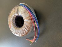
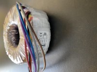
I realize this sounds like a stupid question, but I will ask anyway. I just received my two transformers (I am building mono blocks). They are Avel-Lindberg 18-18 volt 250VA. They came in a box, but appear to be wrapped in a plastic covering. I assume I do not remove that covering, or do I? Here are pictures (they keep showing sideways, I tried rotating them but it does not work):
I realize this sounds like a stupid question, but I will ask anyway. I just received my two transformers (I am building mono blocks). They are Avel-Lindberg 18-18 volt 250VA. They came in a box, but appear to be wrapped in a plastic covering. I assume I do not remove that covering, or do I? Here are pictures (they keep showing sideways, I tried rotating them but it does not work):
Attachments
I left the clear plastic in place. Works no hassle.
Didn't see any advice to remove.
Thoughts from anyone else?
Didn't see any advice to remove.
Thoughts from anyone else?


- Home
- Amplifiers
- Pass Labs
- Aleph J build guide for noobs