Hmmmm I think that might be a better option I just need to buy another power controller for the second case. I am making my own cases just waiting on conrad heatsinks to get back to me I think they must be closed due to covid.
OK, as promised, I've posted the "good build habits" entry to the blog:
Building: Good Build Habits
Comments and suggestions welcome, of course.
Building: Good Build Habits
Comments and suggestions welcome, of course.
I have sent 4 emails no reply I will give them a ring tomorrow thank you for the heads up.
Let me know how you go, I will also call them if you are still having issues.
heatsinks
I tried ringing all day on Friday but phone just rings out. I have considered buying from store but I need 12 heatsinks so the freight is way too expensive.
I tried ringing all day on Friday but phone just rings out. I have considered buying from store but I need 12 heatsinks so the freight is way too expensive.
Not sure if this has been referenced before, but I just stumbled across this on YouTube: First Watt Aleph J Build (Part 1) The Power Supply - YouTube
Pretty good video guide for noobs building an Aleph J. Appears to be in four parts.
He uses mica insulators for the MOSFETS, which he splits to make them thinner - which is pretty funny. Why not just use Keratherm? Haha.
Pretty good video guide for noobs building an Aleph J. Appears to be in four parts.
He uses mica insulators for the MOSFETS, which he splits to make them thinner - which is pretty funny. Why not just use Keratherm? Haha.
Last edited:
In my previous post, I mentioned not really knowing how to use my DMM. I meant this in the sense that, when someone says or writes to “Measure such and such,” I don’t really know which setting on the DMM to use. All those little symbols, they’re confusing to the newb who doesn’t use a DMM everyday.
Here is where experience and actual electronics and tools knowledge comes into play: I ran into a measuring problem on the six 3W .47 ohm resistors at R16-23, such that I didn’t actually know what to do about it.
Like I had done with every other resistor, I set my DMM to its ohm symbol. Since .47 is less than 1, I set the DMM’s dial to its lowest setting: 600. Above that are 6k, 60k, 600k, 6M, 60M. And while I had no problem getting accurate measurements for literally every other resistor, I couldn’t seem to get an accurate reading on these 12 (six per board) resistors.
Thoughts ranging through my head:
- I’m stupid and don’t know how to use this stupid tool
- No way all 12 resistors read the same rating and are also more than 2x high
- Maybe I should try all the other symbols on the dial
- I give up
- I use this for one project every other year, no fcking way I’m buying multiple DMMs
- Maybe my DMM is consistently wrong
- Maybe I’m not making good contact on the leads/legs
- Maybe I should switch red and black
- Maybe Mouser was wrong
- Ugh, do I really need to buy 12 more of these?
To be clear, my DMM kept reading anywhere from .9 to 1.2. With a 5% rating, this writer’s non-mathematical mind says that a .47u resistor should be +/- a decimal number I can’t actually fathom, such that the reading wouldn’t be higher than .5 on the high side, let alone anywhere close to .9 - 1.2.
A forum member who reached out to me previously in a DM, when I asked him about measuring, said I should be okay:
“You're measuring it properly. Measurement accuracy/precision for anything below ~10 ohms on a standard hand-held DMM is going to be very challenging… I am confident enough to tell you not to worry about it. My recommendation is to install them as-is and don't give it another thought.”
On the BG’s post #4 recap, I clicked on the link to #1015, “how to test trimpot” resistance once on the PCB. I followed this example for the 12 (six per board) 3w .47 ohm resistors and got measurements of .4-.5 for every one of them.
Pictures of my build progress on my Instagram page, @13stoploss.
The other member who said don't worry about it is correct. If you bought brand-name resistors, it is highly unlikely that they are not the right values.
The issue is probably your DMM leads. Crappy leads can often add to resistance measurements and/or result in inconsistent readings at low settings. Suggest you upgrade your leads. I had a set of leads that were showing 1 Ohm when shorted together. Even though they looked fine, they were junk. New leads showed between 0 and .1 Ohms. Of course the jacks on your DMM could have some oxidation also, which can be helped with DeoxIt or other contact cleaner.
Finally, consider upgrading your DMM if it is old or not great. Perfectly good DMMs can be had for $30-$40. There are suggestions elsewhere in the forum.
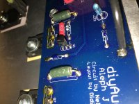
Something I just learned and don't remember if I did correctly: the LED's long leg is positive. On the amp board where the LED goes, there are two round circles. One side of the circles has a flat spot, like if a car that sat for years in a field had a flat, but then you moved the car a few inches forward so that the flat spot is on the side instead of on bottom. That flat side is where the long leg goes.
It looks like this: https://startingelectronics.org/beginners/components/LED/LED-polarity.png
Mentioning here because it, too, is not in the BG. If a newb like me has that question, there are sure to be others. Well, to be honest, I didn't even know that LEDs had polarity differences and I later discovered they did...
Unfortunately, it's impossible to tell from markings alone which side is the "flat" side on the PSU board. The solder pads break up circles so that both sides are identical. I ended up putting the anode (oooh, big word! [long leg]) into the side that had foil tracings in the board. Can I get a double check on this?
The long leg, (anode, +) needs to go into the PCB pad that is more positive.
On the V+ rail it’s straightforward... the long leg needs to connect to V+ and the cathode to ground.
It’s a little bit of a logic jump on the V- side, as ground is actually more positive than V-. So the anode needs to connect to the pad attached to ground and cathode to V-.
Also worth noting, the location of the resistor doesn’t matter, it can be on either leg.
Last edited:
The long leg, (anode, +) needs to go into the PCB pad that is more positive.
On the V+ rail it’s straightforward... the long leg needs to connect to V+ and the cathode to ground.
It’s a little bit of a logic jump on the V- side, as ground is actually more positive than V-. So the anode needs to connect to the pad attached to ground and cathode to V-.
Also worth noting, the location of the resistor doesn’t matter, it can be on either leg.
I had to read this multiple times to make sense of it. By the sixth or seventh try, it was clear to me what you meant. Thank you.
Great advice, everyone, thanks! We will make revisions.
And I will ask on 6L6's thread what the C9 cap actually does, so we can explain it accurately. 🙂
Am I missing where a potential C9 mounts on the PSU? I also don't recall (or missed) it on the PSU BOM.
Snubbers may not be strictly necessary, but they are a nice little add-on for peace of mind. The basic is a simple 0.01 uF film cap across each secondary winding at the input of the bridge rectifier. I also usually add a 2.2 uF film cap across the DC output of each bridge rectifier to handle higher frequency switching noise that may not be adequately filtered by the large bulk caps, as they tend to have an inductive component due to their physical size.
I see it's recommended to not use optional snubbers at R11-12 and C17-18. As I've snapped off the diode section of my PSU 3.0 and bought the GBPC3506 bridges, I was hoping you could explain more about where the optional but recommended snubbers CS1-2, CX1-2, RS1-2 would mount/attach. I've purchased Antek 4218, and the Quasimodo figures are Cx=10nf, Cs=150nf, Rs=18ohm. Unfortunately, my 4U steel black chassis is 300mm deep, no backside faceplate holes.
The transformer wiring runs underneath the transformer mounting plate and power supply PCB.
The secondaries' wiring runs from the transformer to the front of the amplifier, because the length of this low voltage AC wiring is not important (it is least harmful to the amplifier operation/specifications); what IS very important is the length of the DC wiring. By orienting the power supply PCB in this way, I have managed to reduce the DC wiring to the bare minimum.
The CL-60 is soldered directly to the IEC filter legs. There is plenty of room for it to run reasonably cool (determined by the nominal current that runs through it anyway).
The mains wiring length is only 10cm.
For the OP: blog idea/addition: explain what mains and secondairies means, and which is AC and which is DC. I can and will Google it, but just saying...
... I've purchased Antek 4218, and the Quasimodo figures are Cx=10nf, Cs=150nf, Rs=18ohm. Unfortunately, my 4U steel black chassis is 300mm deep, no backside faceplate holes.
....
I also have the 300mm with the black frontpiece (and therefore no mounting holes). I just purchased this:
Omega-Bracket – Toroid
The #5 will work for a 5.1" diameter Antek 400VA 18 or 20v. It flexes and comes with long screws and a rubber collar. They're a very nice vendor- but charge too much for shipping (unless you pick up in person in MD).
BTW, I appreciate your posts- I'm very much a newbie here too (last electronic project I did was solder together a passive XO for a pair of book shelf speakers.) I was thinking of building the F6 b/c it's so simple, but I read the Alpeh J is a better sound- and with this blog and BOM, I'm leaning toward it (h/t OPs!).
Just wanted to jump in and say that I'm also a noob that will be building an Aleph J along with you. I'm fairly confident with soldering and passable at reading schematics, but you're absolutely right, there's just an overwhelming amount of data to consume. So thanks for doing this! I've already learned a ton from this.
I also have the 300mm with the black frontpiece (and therefore no mounting holes). I just purchased this:
Omega-Bracket – Toroid
The #5 will work for a 5.1" diameter Antek 400VA 18 or 20v. It flexes and comes with long screws and a rubber collar. They're a very nice vendor- but charge too much for shipping (unless you pick up in person in MD).
Ohhhh, that looks awesome! Thanks! I'm actually in Maryland, but Salisbury is a 2-3 hour drive. Still, I'm intrigued...
*Edit: #5 is currently on backorder: Omega Bracket #5 Kit – Toroid
Last edited:
Four minor questions
I'm well into building my Aleph J now, having completed the power supply psb and started the first amp board. So far it's been pretty straightforward, following the original build guide and referring to the BoM, but four issues have arisen about which I'd very much appreciate some guidance.
1. C6 and C7. The parts that Mouser sent, which match the recently posted BoM, have incorrect pin spacing, 10mm instead of 5mm. I stumbled across some discussion deep into the 500+ pages of the original guide that suggested these could in fact be left out. Can someone confirm this? If, so, should jumpers be used instead?
2. Smaller MOSFET orientation. I can't find where this has been specified, but it must be obvious to those more experienced than I am. I've searched for and enlarged a number of pictures of completed boards, and see what appears to be both orientations represented. I found no link in the DIY store's listing to a spec sheet, but perhaps I just don't know where to look.
3. In some photos there is a zip tie around the paired JFETs. Is this advised? If so, why?
4. R8 appears to be alternately filled with a jumper or a pot. What are the pros and cons of this decision?
Many thanks in advance for any advice you can provide. 😉
The input j fets should be held together with some heat shrink or a zip tie and a bit of thermal paste between them. Helps them stay the same temperature
Some closeup pics might help for orientation. You should look up the data sheet for the device your using and note the pin out. Then use the schematic to verify the orientation.
The circuit will work without c6 and c7
Some closeup pics might help for orientation. You should look up the data sheet for the device your using and note the pin out. Then use the schematic to verify the orientation.
The circuit will work without c6 and c7
Attachments

Thanks, evanc, for the quick and helpful reply. The closeup photos were great at showing orientation of the transistors.
My questions were in part to address what I understand to be the overall purpose of this thread, to help flohman and alanhuth in preparing a new build guide for 'noobs', like me. For others like me moving along from building a pair of ACAs, details like orientation of transistors are essential. Similarly, situations where the builder has more than one option (e.g. insert a pot or a resistor) require a bit more background than we are likely to bring. I'm thoroughly enjoying acquiring this background, and very much appreciate this thread and the willingness of those of you more learned and experienced to help us new folks build our skills. And in the case of the Aleph J, an amazingly capable amp!
My questions were in part to address what I understand to be the overall purpose of this thread, to help flohman and alanhuth in preparing a new build guide for 'noobs', like me. For others like me moving along from building a pair of ACAs, details like orientation of transistors are essential. Similarly, situations where the builder has more than one option (e.g. insert a pot or a resistor) require a bit more background than we are likely to bring. I'm thoroughly enjoying acquiring this background, and very much appreciate this thread and the willingness of those of you more learned and experienced to help us new folks build our skills. And in the case of the Aleph J, an amazingly capable amp!
Happy I could be a help.
For r8 I have a potentiometer. Maybe someone more knowledgeable can chime in on what a good value fixed resistor could be used in this position
Like I said I really think it’s good to get the data sheet for all the active parts and note the pin out. I usually sketch a picture right on my printed out schematic. Then go to the schematic and board and figure out how things should be oriented. It’s important because Sometimes we can inadvertently choose parts with different configurations then previous builders.
The long leg, (anode, +) needs to go into the PCB pad that is more positive.
On the V+ rail it’s straightforward... the long leg needs to connect to V+ and the cathode to ground.
It’s a little bit of a logic jump on the V- side, as ground is actually more positive than V-. So the anode needs to connect to the pad attached to ground and cathode to V-.
Also worth noting, the location of the resistor doesn’t matter, it can be on either leg.
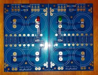
Interesting. So if I'm interpreting you and reading the board correctly, that means that the LED long leads should be on the left on both V+ and V- (per the photo), yes?
Also, I was planning to use leftover component leads as the jumpers for the four ground connections between the left and right sides of the PSU board. Will that be good enough, or should I scrounge up some solid core copper wire?
Attachments
- Home
- Amplifiers
- Pass Labs
- Aleph J build guide for noobs