Start with mono aural testing - is it the same L=R same source?
Try with a simple square wave input, increase freq and watch leading/trailing edges.
Should NOT ring. Should "gracefully slur" corners at upper end.
Post pics at 1k, 10k, 20kHz ...
mark
Try with a simple square wave input, increase freq and watch leading/trailing edges.
Should NOT ring. Should "gracefully slur" corners at upper end.
Post pics at 1k, 10k, 20kHz ...
mark
Mark, referring to the circuit diagram, I have followed your recommendations. C11 is a Tantallum SMD capacitor (normally chosen because tantallum doesn't mind continuous operation at low voltage). C4 and C7 are Silvered Mica, C7 (C1 on circuit) is MKPS Polyethelylen MKPS4. C8 and C9 are nothing special but low ESR Panasonic 220uF/35V.
All resistors are vishay R55 1%, with the exception of the Source resistors which are 1% 3W Metal Oxide.
All MOS-FETs were matched, in groups, to within 1% of each other.
All resistors are vishay R55 1%, with the exception of the Source resistors which are 1% 3W Metal Oxide.
All MOS-FETs were matched, in groups, to within 1% of each other.
Sig. Gen. is in the loft at the moment. I'll break it out tomorrow and do some phots with In/Out at 1-10-100KHz.
Andy
Andy
The oscilloscope is quite revealing.
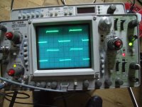
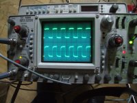
At 1kHz and 10KHz things aren't too bad. At 60KHz things are starting to go wrong.
OK my signal source is not perfect, but could this be the problem ?
These are boards made using Mark's design ???
In all traces, the upper trace is the input and the lower trace is the output with the speakers connected.
Attachments
the transformers are getting WARM, not HOT. This may just be down to the 2.4A quiescent current.
I can't see any oscillation at the outputs.
I can't see any oscillation at the outputs.
With plastic or even nonmagnetic screws, maybe with PVC binding belts,...How else would you suggest mounting them.
But, first of all, I would make a try with inductance measure (with and without metal screw), or, at least, to make an audible test.
No further ideas... 😀
Again, congrats to your work!
 & for fun!
Please don't run 60kHz SW into your speakers ...
We don't expect a SW at 60kHz, the design uses the FET capacitance etc to gently roll-off the upper end - especially when this sees the load of the speakers.
What you see looks normal. (to me!)
Have you tried listening R<>L mono ... are both channels identical?
Random failure/misadventure is highly unlikely to be duplicated exactly in both channels.
Cheers
Mark
With plastic or even nonmagnetic screws, maybe with PVC binding belts,...
But, first of all, I would make a try with inductance measure (with and without metal screw), or, at least, to make an audible test.
No further ideas... 😀
Again, congrats to your work!
I'll try removing them altogether to start with. The diagrams that I have been following simply use CCC smoothing. This will also increase rail voltage closer to the recommended +/-48V
OK. I've borrowed a decent Sig Gen from work.
The results aren't too much different from those obtained yesterday.
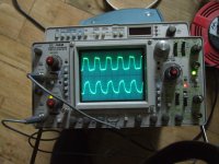
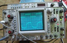
Pic1 is Right Ch at 500mV and 50KHz.
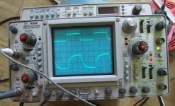
Pic2 is Right Ch at 500mV and 100KHx
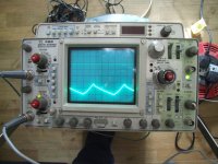
Pic3 is Left Ch at 500mV and 100KHz
Top trace is 500mV input - bottom trace is output (no speakers attached).
I have removed the Chokes from the PSU leaving 100000uF CCC per rail - 4 rails in total.
The TSSSSS is present on both channels.
There are three 220uF caps in the Aleph 4. C8 and C9 are in the current source and C11 is on the -ve INPUT.
Mark Finnis recommended a tantalum for C11. I'm starting to think these may be the cause of the trouble. I am using the amp unbalanced.
The results aren't too much different from those obtained yesterday.
Pic1 is Right Ch at 500mV and 50KHz.
Pic2 is Right Ch at 500mV and 100KHx
Pic3 is Left Ch at 500mV and 100KHz
Top trace is 500mV input - bottom trace is output (no speakers attached).
I have removed the Chokes from the PSU leaving 100000uF CCC per rail - 4 rails in total.
The TSSSSS is present on both channels.
There are three 220uF caps in the Aleph 4. C8 and C9 are in the current source and C11 is on the -ve INPUT.
Mark Finnis recommended a tantalum for C11. I'm starting to think these may be the cause of the trouble. I am using the amp unbalanced.
Attachments
I don't know if my ears are deceiving me. I've tried the amp with the Pumpkin left out of circuit, ie the CD player feeding the passive ladder attenuator and then the amp.
It might just sound slightly better ??????
It might just sound slightly better ??????
Looks OK
I use CLC ... rails much quieter. Since you have the CRO you could actually measure the difference ... just for fun 🙂
One of the "benefits" of the Pass amps is obtaining a really clear image of pre-amp performance!
mark
I use CLC ... rails much quieter. Since you have the CRO you could actually measure the difference ... just for fun 🙂
One of the "benefits" of the Pass amps is obtaining a really clear image of pre-amp performance!
mark
The ripple on the rails with CCC or CLCC is very much the same. About 40mV of ripple.
I've got one channel with CLCC and the other with CCC at the moment. I'll post some pics later.
I've got one channel with CLCC and the other with CCC at the moment. I'll post some pics later.
Some things work fine without preamp, but I found many other aspects that are worse.
you must do a longer hearing.........
normally bass, dynamics and colors are less distinct, but voices "room feeling" and articulation may be better......
you must do a longer hearing.........
normally bass, dynamics and colors are less distinct, but voices "room feeling" and articulation may be better......
What are we looking for on the suppkly rails ? the ripple is absolutely tiny compared with the load.
Taking all attenuation out of the way and feeding the Aleph4 straight from the output of the CD36 is much more pleasant. It's too loud to hear if the sibilance has disappeared but the problem my be an impedance issue.
WIERD. Without the Pumpkin/Shuntky. the Mains Transformers are running COOL.
Something must be oscillating somewhere, I can't see it in the Aleph 4 though.
Something must be oscillating somewhere, I can't see it in the Aleph 4 though.
I can't understand why the transformers 2 x 500VA run v.warm with the PUMPKIN attached but run almost COLD with the PUMPKIN out of circuit.
Common sense would say that the PUMPKIN is oscillating. I can't find any trace of oscillation with the 'scope.
Common sense would say that the PUMPKIN is oscillating. I can't find any trace of oscillation with the 'scope.
I use pumpkin with Aleph 2 monoblocks and nothing is overheating and oscillating. In your case, I'd draw detailed schematics of ground connections and try to find out if there are any currents running through grounding wires between preamp and power amp. Also check if there are any ground loops and draw grounding connections in both Aleph and Pumpkin/Shunty channels. If you have different levels of ground potential between Aleph and Pumpkin it could cause the situation that some current is running through grounds causing problems you face.
I'll let the pictures speak for themselves.
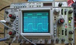
Channel 1 is CLCC
Channel 2 is CCC
Both are set up identically on the 'scope.
There is a clear ripple on the CCC which is completely absent on the CLCC.
Wether or not this is audible is still debateable.
Channel 1 is CLCC
Channel 2 is CCC
Both are set up identically on the 'scope.
There is a clear ripple on the CCC which is completely absent on the CLCC.
Wether or not this is audible is still debateable.
Attachments

- Status
- Not open for further replies.
- Home
- Amplifiers
- Pass Labs
- Aleph 4 Strickly DIY Project Build