Hi Do,
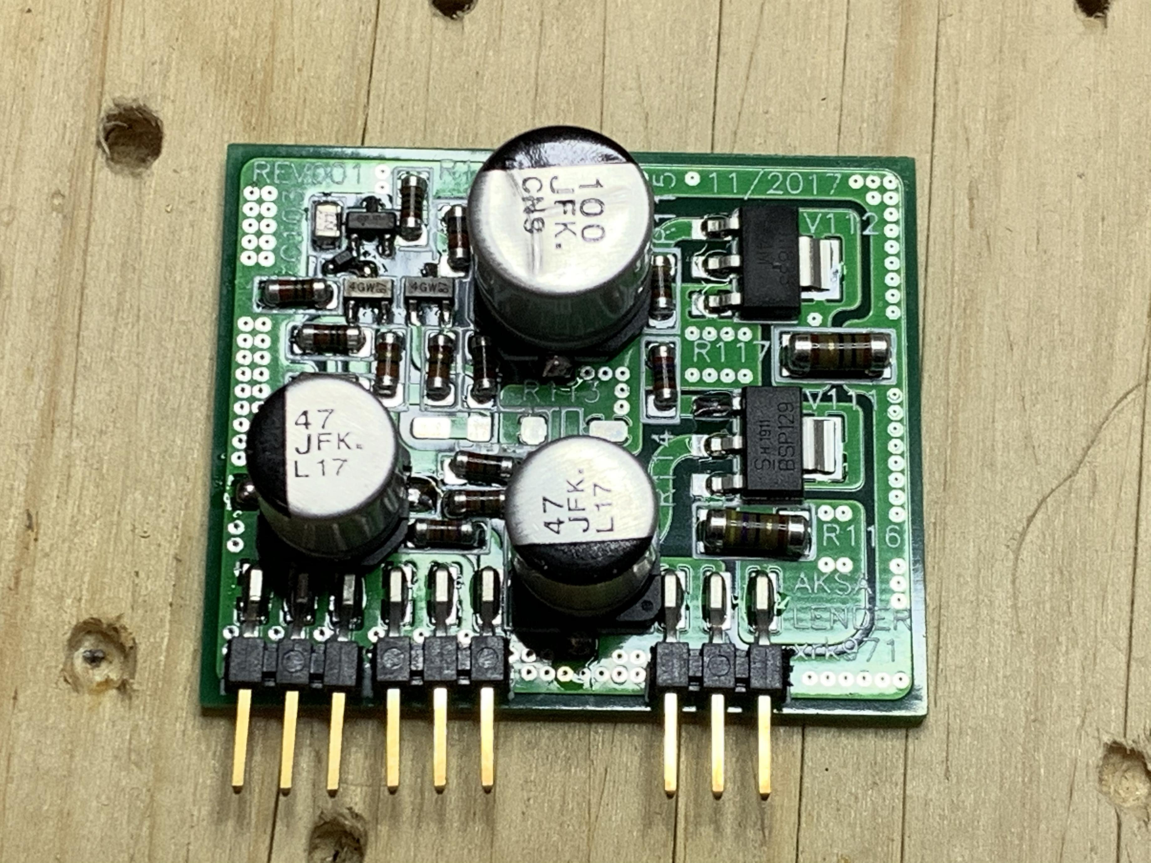
Nice work on the SMT soldering! Your probably saw this, but I think your diode is lifted up on one end and crooked. I agree that this part is a bit tight and too close to the BJT and resistor.
X
Nice work on the SMT soldering! Your probably saw this, but I think your diode is lifted up on one end and crooked. I agree that this part is a bit tight and too close to the BJT and resistor.
X
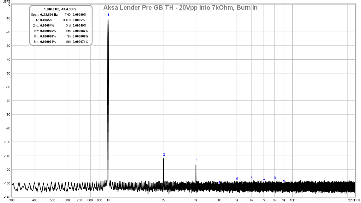
My vote goes to Vishay metal foil, check out my measurements at https://www.diyaudio.com/forums/gro...der-preamp-40vpp-ouput-gb-41.html#post5576044. Like Vunce said, this one is a tweaker's dream!
Greg
Thanks for reminding me about your boutique metal foil resistors. I never appreciated the fact that they took the THD down from 0.009% to 0.002% and left it H2 dominant vs the ohmite's. That is worth $20 for a pair of 600mW resistors! The Ohmite's were carbon composition and got higher H3 - which was different than my experience with carbon film which brought out a higher H2 vs H3. Maybe carbon film is different than carbon composition.
Last edited:
Carbon comps have probably the highest temperature coefficient of any resistor type (~1500 ppm/K). It is hardly a surprise to be seeing increased H3 with these. Carbon film is a bit better if memory serves (500-750 ppm/K?), and metal film is substantially better than both (~100 ppm/K, at times down to 1 ppm/K). Bulk foil can achieve superb TC (<1 ppm/K). Thick film is similar to carbon comp, thin film is similar to metal film. Linearity will improve with higher wattage in any type (as even at same TC, self-heating is reduced). Excess noise characteristics rank in a very similar manner.
Aging in carbon comps can be very poor unless their packaging keeps out moisture well, as anyone restoring old gear from about the 1960s and earlier will be able to attest. In short, aside from a few niche applications like ESD protection, carbon comps are generally a poor choice these days.
Basically you're excited because your Ferrari is a lot faster than a basic city bike. Well, duh. You didn't even try a Toyota Corolla (or in this context, plain metal film / thin film).
I recommend taking a look at AD's Op Amp Applications, Chapter 7.
Last edited:
I forgot that using basic no name brand carbon film, I was able to get 0.001% THd for 20Vpp into 7kohms. This is on post 1:
off topic question
I got my attention caught on the aka lender, that sounds like a (more than) perfect companion for a F4...
But may I ask about those resistor-standoffs, what are these? are these standard parts, available @ mouser?
thanks!
I got my attention caught on the aka lender, that sounds like a (more than) perfect companion for a F4...
But may I ask about those resistor-standoffs, what are these? are these standard parts, available @ mouser?
thanks!
Hi Do,
Nice work on the SMT soldering! Your probably saw this, but I think your diode is lifted up on one end and crooked. I agree that this part is a bit tight and too close to the BJT and resistor.
X
Hi X,
You're right but the pad is connected there as well, so I decided to leave it as is.
Do
I got my attention caught on the aka lender, that sounds like a (more than) perfect companion for a F4...
But may I ask about those resistor-standoffs, what are these? are these standard parts, available @ mouser?
thanks!
This is the only place I've been able to find them:
1001-11, tinned solder terminal | Burklin Elektronik
Excellent, thank you!
When I do smd by hand (soldering iron), I can really align all the parts straight and make it even nicer but it takes way two much time this way. Rework station works nice and parts alignment is not as critical if only for my own eyes!
I would definitely use a stencil if you make some for other projects.
Do
I would definitely use a stencil if you make some for other projects.
Do
It‘s those little details that make building stuff so fun 🙂
Thanks very much, X
When I do smd by hand (soldering iron), I can really align all the parts straight and make it even nicer but it takes way two much time this way. Rework station works nice and parts alignment is not as critical if only for my own eyes!
I would definitely use a stencil if you make some for other projects.
Do
If you apply paste by syringe and needle, a hot plate and hot air will pretty much align parts automatically by surface tension. You can nudge stuff around with a tool while it’s on the hot plate to make alignment perfect. Soldering iron can never give beautiful solder fillets between the part and the pad like paste and hot plate or hot air rework station.
If you apply paste by syringe and needle, a hot plate and hot air will pretty much align parts automatically by surface tension. You can nudge stuff around with a tool while it’s on the hot plate to make alignment perfect. Soldering iron can never give beautiful solder fillets between the part and the pad like paste and hot plate or hot air rework station.
You're right but I find that when using a stencil, parts stay in their position much better and align better due to even paste distribution. I will definitely invest in a hot plate in the coming weeks.
Do
Ok, looks like @ 46.5Vdc supply (after CapMX), max limit input is 1.1Vac. This is tested with 10K sine wave as input. Sounds about right?
Gain is set at 27dB
Just want to make sure I’m all good. Square wave is almost perfectly square even above 20K @ 1.1V
Gain is set at 27dB
Just want to make sure I’m all good. Square wave is almost perfectly square even above 20K @ 1.1V
Nice work, Do! Any photos of your new baby?
I forgot what you were you going to drive with this preamp - was it MOFO?
I forgot what you were you going to drive with this preamp - was it MOFO?
Hi X,
I have photos that I will post later but don’t have a chassis yet. With Chinese New Year and coronavirus, it is almost impossible to get a chassis delivered... Unfortunately, until then, it will sit on a plywood piece...
Yes, it will be used to drive the MOFO but I was toying with the idea of assembling another set of SMT for use on regular (non buffer) amplifiers. So much lower gain and voltage swing. What are your thoughts on this?
Thanks
Do
That’s one of the traits that makes this preamp so good, versatility! Use your high gain DB’s for driving MoFo type amps, swap in a low gain DB and dial back the voltage to drive “regular” type amplifiers. 😀
I have two Aksa Lenders, one at 27dB and the other at 12dB. Swapping DB's is pretty easy too. For the Aksa Lender (LTP front end with AL VAS and CCS and BJT output), it needs the 48v to work as designed so no voltage adjustment necessary for the lower gain one. Just change the ground shunt resistor (Ri) and leave feedback resistor (Rf) alone. Be sure to use carbon film on the feedback resistor for the correct balance of second vs third harmonic distortion.
When using the Main Board (MB) with a PCA DB, then the voltage needs to drop to 24v.
When using the Main Board (MB) with a PCA DB, then the voltage needs to drop to 24v.
Here's a couple pictures in test. The volume pot will be replaced by TKD sinc ethis one is a 3$ cheapo pot.


Just missing the chassis. I have two builds in there (not showing both), one for a friend and one for me.
Do
Just missing the chassis. I have two builds in there (not showing both), one for a friend and one for me.
Do
- Home
- Source & Line
- Analog Line Level
- AKSA's Lender Preamp with 40Vpp Output