Hi
What is the minimum and the maximum gain recommended for this preamp?
And what is the recommended values for R10 and R11 for the max and min gain?
Reg.
What is the minimum and the maximum gain recommended for this preamp?
And what is the recommended values for R10 and R11 for the max and min gain?
Reg.
It works well with anywhere from 3x gain to 10x gain (needed to get amp to clip at 40Vpp).
Referring to this schematic:
Gain is set by G=(R10+R11)/R11
Hugh may have good suggestions for values that would optimize imaging. But to first order, setting R11 at 1k and changing R10 per the above equation is not too bad. Conversely one can leave R10 at say 10k and adjust R11.
Referring to this schematic:
Gain is set by G=(R10+R11)/R11
Hugh may have good suggestions for values that would optimize imaging. But to first order, setting R11 at 1k and changing R10 per the above equation is not too bad. Conversely one can leave R10 at say 10k and adjust R11.
Last edited:
Ideally you would reset the compensation each time you adjust the gain.
It is better to use R10 at 33k to match the value of R1. This balances the voltages at the bases of the LTP, and therefore the offset.
Best change to adjust the gain with R11. If you used R10 at 33k, you could use R11 from as low as 2k2 (giving gain of [33k+2k2]/2k2 = 16) and as high as 15k (giving gain of [33k+15k]/15k = 3.2).
I am pretty sure that C5 = 33pF NPN is OK, but you would need to test it on the bench with a CRO to look for instability. This is a very fast amp because of the way the VAS is configured, so less rather than more compensation is required. The R9 68k resistor is used to reduce the open loop gain, but at very low gain (less than 5) you might put another compensation cap of 5pF across it.
Thanks X!
HD
Hello Hugh,
I hope all is well in your part of the world🙂
I was using a set of DB’s with values of:
R9 100K
R10 12k
R11 1K
Reading your last post I decided to tweek a bit,
Now the values are:
R9 68K
R10 33K
R11 2k2
Question, should I lower C5? (Maybe to 27pF)
Also I’m currently using a Wima FKP, would a silver mica be a better choice? Or just experiment 😀
Thanks for such a versatile preamp design, it has not been out of my main system since it’s birth!
Regards,
Vunce
Hi, Hugh.
So you recommend to stay with R10=33k, and change R11 from 2k2 to 15k by the formula R11=R10/[G-1]?
Regards
So you recommend to stay with R10=33k, and change R11 from 2k2 to 15k by the formula R11=R10/[G-1]?
Regards
Last edited:
Stupid question... Is it possible to build a balanced output with this preamp kit?
Yes, but would require a lot of rework. Hugh has a new commercial (not DIY) design for a preamp/HPA that is a simple and elegant Class A with balanced outputs under development (another top secret mission I have been on). It will be available in the near future. Of course, it has a wonderful sound signature.
My AKSA Lender build
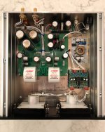
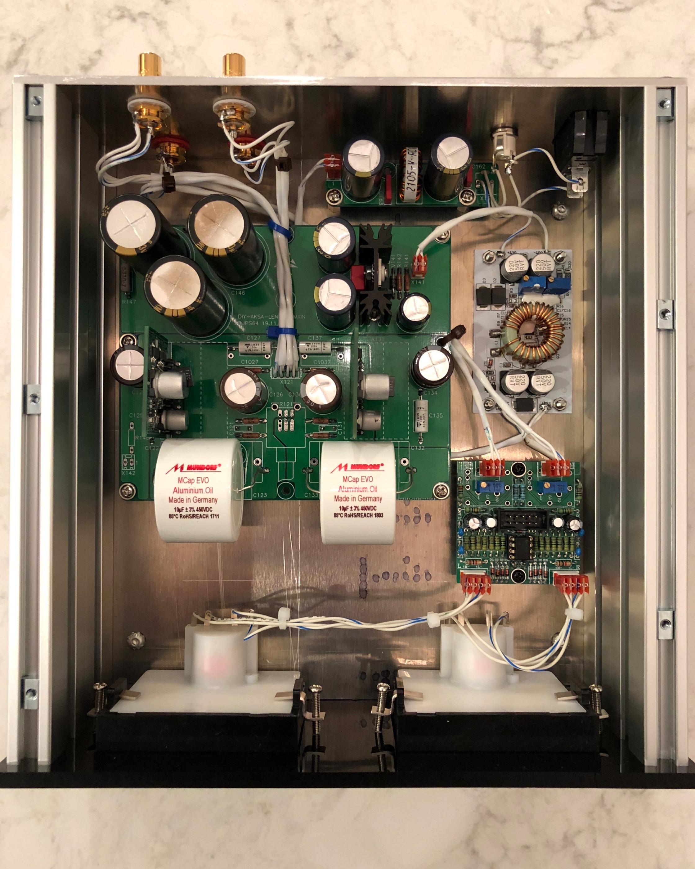
Last week I put the finishing touches on my AKSA Lender build using the 0805/1206 SMT daughterboards. I decided to finally take a break from listening to it and share my build - ok, I am actually listening to it right now!
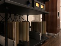
Like many, I am using it to drive my 24v Big Mofo monoblocks. It has plenty of volts to push the Mofo, is dead silent, and I couldn't be happier with the results. The combo has displaced my M2 build and sits proudly in my main listening setup.
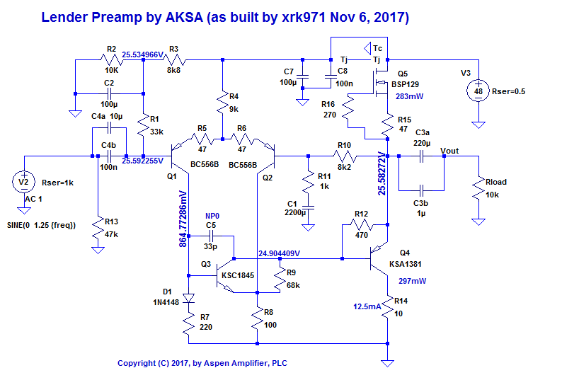
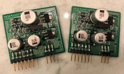
I ran into some interesting results and subsequent tweaking of the daughterboards, specifically R10. My initial selection of carbon composition resistors for R10 was whatever 2 Ohmite OD103JEs that Mouser had sent me. After using these at 5% matching, the gain between the channels was pretty far off. Since these were the only component in the daughterboard with a worse than 1% precision and directly affected the gain, I decided to order 20 of them and find the 2 closest in resistance. After finding a closely matched pair, the gain between the channels was matched fairly close, however THD was higher than I expected at 0.009% at 20vpp.
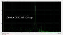
I then took the plunge and ordered a pair of 10k Vishay S102K metal foil resistors. After taking measurements before and after soldering the metal foil in one channel, I was glad I spent the money. THD dropped from 0.009% at 20vpp down to 0.002%. Overall, it was fun to spend money on a ridiculous component and directly see the results 🙂. If any one else is interested, I purchased my pair on eBay for $20.
For other components on the daughterboard, I have attached my BOM as a CSV. All 0805 resistors are Susumu RG, the 1206 resistors are Vishay TNPW e3. Some of the transistors were hard to find, but with an extra order to Arrow and using a BC860C with a smaller SOT-323-3 footprint, I was able to get everything sourced.
For power I am using a 19v laptop SMPS from eBay, the provided CLC filter, and the suggested DC step up to get about 49v. The cap MX takes this down to 45v and I am clipping at 1.45vrms in, 14.1vrms out.
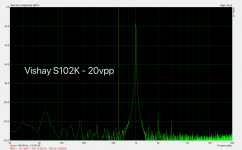
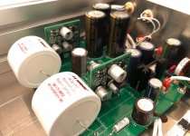
On to case construction. The front panel is milled out of 1/4" cell cast acrylic with VU meters driven by a stereo driver board from JLM Audio. The sides of the case are 15mm wide by 70mm tall extrusions from Misumi. These extrusions are great - I used them for my M2 build as well. They have holes in the front and rear that can be tapped for M5 screws and t-slots for the top and bottom for easy fastening of the panels. Top, bottom, and rear panels are 1/8" 6061 aluminum I milled. One of these days I'll find a place to take my aluminum in for anodization, but until then I've stuck with the raw brushed look.
Please let me know if you have any questions about the build or want me to go into further details!
I want to give a big thanks to X, JPS64, and Hugh for the time and effort that has gone into this preamp and group buy. Thank you for the design, prototyping, manufacturing, and logistics to make this available for us to build and enjoy.
Greg
Last week I put the finishing touches on my AKSA Lender build using the 0805/1206 SMT daughterboards. I decided to finally take a break from listening to it and share my build - ok, I am actually listening to it right now!
Like many, I am using it to drive my 24v Big Mofo monoblocks. It has plenty of volts to push the Mofo, is dead silent, and I couldn't be happier with the results. The combo has displaced my M2 build and sits proudly in my main listening setup.
I ran into some interesting results and subsequent tweaking of the daughterboards, specifically R10. My initial selection of carbon composition resistors for R10 was whatever 2 Ohmite OD103JEs that Mouser had sent me. After using these at 5% matching, the gain between the channels was pretty far off. Since these were the only component in the daughterboard with a worse than 1% precision and directly affected the gain, I decided to order 20 of them and find the 2 closest in resistance. After finding a closely matched pair, the gain between the channels was matched fairly close, however THD was higher than I expected at 0.009% at 20vpp.
I then took the plunge and ordered a pair of 10k Vishay S102K metal foil resistors. After taking measurements before and after soldering the metal foil in one channel, I was glad I spent the money. THD dropped from 0.009% at 20vpp down to 0.002%. Overall, it was fun to spend money on a ridiculous component and directly see the results 🙂. If any one else is interested, I purchased my pair on eBay for $20.
For other components on the daughterboard, I have attached my BOM as a CSV. All 0805 resistors are Susumu RG, the 1206 resistors are Vishay TNPW e3. Some of the transistors were hard to find, but with an extra order to Arrow and using a BC860C with a smaller SOT-323-3 footprint, I was able to get everything sourced.
For power I am using a 19v laptop SMPS from eBay, the provided CLC filter, and the suggested DC step up to get about 49v. The cap MX takes this down to 45v and I am clipping at 1.45vrms in, 14.1vrms out.
On to case construction. The front panel is milled out of 1/4" cell cast acrylic with VU meters driven by a stereo driver board from JLM Audio. The sides of the case are 15mm wide by 70mm tall extrusions from Misumi. These extrusions are great - I used them for my M2 build as well. They have holes in the front and rear that can be tapped for M5 screws and t-slots for the top and bottom for easy fastening of the panels. Top, bottom, and rear panels are 1/8" 6061 aluminum I milled. One of these days I'll find a place to take my aluminum in for anodization, but until then I've stuck with the raw brushed look.
Please let me know if you have any questions about the build or want me to go into further details!
I want to give a big thanks to X, JPS64, and Hugh for the time and effort that has gone into this preamp and group buy. Thank you for the design, prototyping, manufacturing, and logistics to make this available for us to build and enjoy.
Greg
Attachments
-
 aska-carbon-comp-20vpp.png80.3 KB · Views: 538
 -
 aska-foil-20vpp.png68.5 KB · Views: 545
 -
 aksa-1.jpg582.5 KB · Views: 533
 -
 aksa-2.jpg704.7 KB · Views: 537
 -
 aksa-3.jpg615.9 KB · Views: 789
 -
 aksa-4.jpg918.5 KB · Views: 331
 -
 aksa-5.jpg759.3 KB · Views: 306
 -
 aksa-mofo.jpg743.2 KB · Views: 880
 -
AKSA Lender OAL Bom - 0805-1206 SMD Daughterboard.txt1.3 KB · Views: 106
Hi Greg,
Thanks for sharing pics and details of your build.
If I may ask, what are you using for THD measurements?
Thanks for sharing pics and details of your build.
If I may ask, what are you using for THD measurements?
I'm sure I answer for X and JPS that we have been thrilled this product has been so successfully and brought good audio to the forum members!
Beautifully built, Greg.......
Hugh
Beautifully built, Greg.......
Hugh
Gtose,
Simply, a masterpiece of a build. True craftsmanship and perseverance to eek out the last bit of performance. Thanks for sharing the details and BOM. Very cool $20 2ppm stable resistors. Never seen such expensive little suckers but I would say, they are worth it! Even the harmonic distortion profile changed from 3rd order dominant to 2nd order, so a great result all around. 0.002% THD and a profile like that with 20vpp is not easy to get. I live your case!
How are you controlling volume as I do not see a pot? I guess your DAC is the volume knob?
Gtose,
Very inspiring build! Although I have my own thoughts for the “gain” section on my MOFO build, I am most excited about using an AKSA Lender Pre for an F4 based design.
Awesome work, bravissimo!
Anand.
Very inspiring build! Although I have my own thoughts for the “gain” section on my MOFO build, I am most excited about using an AKSA Lender Pre for an F4 based design.
Awesome work, bravissimo!
Anand.
Gtose,
Simply, a masterpiece of a build. True craftsmanship and perseverance to eek out the last bit of performance. Thanks for sharing the details and BOM.
+1
Thanks all for the kind comments.
My current setup is a Linear Audio autoranger, ESI Juli@ soundcard for both input and generator, and ARTA. I have the parts for Frex's EOSC10kv3 oscillator to use as a low distortion generator, I just need to find some more time for assembly.
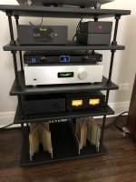
You are right, I jumpered the volume pot pins. An extended view of my setup is attached. Input attenuation and source selection is handled by a preamp that my brother (@loafimus) and I each built earlier this year. It is based off of Jos van Eijndhoven's RelaixedPassive relay stepped attenuator and source selector and Salas' DCG3. We built it with flexibility in mind to support an external buffer such as the AKSA, adding selectable outputs. One output goes through the DCG3 buffer and the other is a passive output after the resistor ladder attenuation. More details about the preamp are on Reddit at The Super-Duper Preamp. : diysound.
If I may ask, what are you using for THD measurements?
My current setup is a Linear Audio autoranger, ESI Juli@ soundcard for both input and generator, and ARTA. I have the parts for Frex's EOSC10kv3 oscillator to use as a low distortion generator, I just need to find some more time for assembly.
How are you controlling volume as I do not see a pot? I guess your DAC is the volume knob?
You are right, I jumpered the volume pot pins. An extended view of my setup is attached. Input attenuation and source selection is handled by a preamp that my brother (@loafimus) and I each built earlier this year. It is based off of Jos van Eijndhoven's RelaixedPassive relay stepped attenuator and source selector and Salas' DCG3. We built it with flexibility in mind to support an external buffer such as the AKSA, adding selectable outputs. One output goes through the DCG3 buffer and the other is a passive output after the resistor ladder attenuation. More details about the preamp are on Reddit at The Super-Duper Preamp. : diysound.
Attachments
Awesome Build!!
Greg,
You really did a fabulous job on the Aksa Lender Pre!! Attention to detail is amazing, milled name in the faceplate is so cool 😎
Now just enjoy sweet music......... while reading notes for the next project that probably has already started 😀
Cheers G!!
Best,
Vunce
Greg,
You really did a fabulous job on the Aksa Lender Pre!! Attention to detail is amazing, milled name in the faceplate is so cool 😎
Now just enjoy sweet music......... while reading notes for the next project that probably has already started 😀
Cheers G!!
Best,
Vunce
Hi Greg,
fantastic build and you used good quality resistors through out. I never cared for carbon.
I am curious as to why you didn't use a 33K value for R10 as Hugh suggested in post 403?
fantastic build and you used good quality resistors through out. I never cared for carbon.
I am curious as to why you didn't use a 33K value for R10 as Hugh suggested in post 403?
Hi Greg,
Great build, enjoy it!
May I ask which part# are these red sockets you are using on VU Meter driver board?
Great build, enjoy it!
May I ask which part# are these red sockets you are using on VU Meter driver board?
I am curious as to why you didn't use a 33K value for R10 as Hugh suggested in post 403?
I wanted the originally specified 20dB of gain for the Mofo, so simply went with the values from the original BOM since. I figured the other calculations were for a base to modify to other gains and decided to go with what had already been tested and measured by X and others.
May I ask which part# are these red sockets you are using on VU Meter driver board?
Glad you asked! They are TE's MTA-100 series: MTA-100 Series - TE Connectivity AMP Connectors - Free Hanging, Panel Mount | Online Catalog | DigiKey Electronics. The red ones are for 22AWG wires, they have other wire sizes available as well as 0.156" pin spacing.
They are my new favorite connectors and have been using them - in addition to fastons/quick-disconnects - for all of my wire-to-board needs. Conveniently, they have 0.1" pin spacing so are largely compatible with typical 0.1" pin headers of lesser quality. They are also locking and polarized! One would think I am a TE salesperson, but I just really enjoy them over other 0.1" crimp headers which I can never seem to terminate correctly no matter how hard I try or spend on crimpers.
The downside is since they are IDC, they do require a special tool to correctly terminate. They offer an not-so-horribly priced insertion tool that will get you there: 59803-1 TE Connectivity AMP Connectors | Tools | DigiKey.
Given my enthusiasm for them, I actually splurged for a spring-based crimp head and corresponding hand tool. Luckily the combo can be found used on eBay for around $80-100.
Glad you asked! They are TE's MTA-100 series: MTA-100 Series - TE Connectivity AMP Connectors - Free Hanging, Panel Mount | Online Catalog | DigiKey Electronics. The red ones are for 22AWG wires, they have other wire sizes available as well as 0.156" pin spacing.
Thanks! Will put some of these connectors (with gold contact finish of course) and the T-Handle Tool on my shopping card when I order next time at digikey.
What I like about this forum is that I often get new ideas and details like this which I can use for my next projects.
- Home
- Group Buys
- AKSA's Lender Preamp with 40Vpp Ouput GB