Congratulations, Alan! I think you need a 350 x 100 heatsink with vertical, spaced fins. I use the Conrad sinks, cast here in Melbourne. They work very well.
As the caps bed down, you will have a great amp for keeps providing you have reasonably sensitive speakers. Can you hear the spatial qualities of this amp? How is the depth of image?
Hugh
As the caps bed down, you will have a great amp for keeps providing you have reasonably sensitive speakers. Can you hear the spatial qualities of this amp? How is the depth of image?
Hugh
Heatsinks,yes. I was trying to use what I had available, I will have to save my pennies and buy the correct type. I'm still very much in the construction stage and I do not believe I am qualified enough to give detailed analysis of how the Alpha sounds, what I will say is I am impressed enough to make this my main amplifier( when finished) taking the place of my Krell clone. Really nice amplifier.
Thank you.
If I read correctly one of your previous posts 1951 must have been a vintage year, snap.
Regards
Alan.
Thank you.
If I read correctly one of your previous posts 1951 must have been a vintage year, snap.
Regards
Alan.
Hugh,
Thank you for the guidance on the heat-sinks and thermal management. Understand from the following post that with 1.6 amp bias the ALPHA 20 dissipation per channel will be ~77 watts:
http://www.diyaudio.com/forums/soli...rid-aleph-alpha-amplifier-78.html#post5360322
The Conrad heat-sinks you shared as an example have the fins vertically oriented, so the hot air can rise and escape faster; a 100 x 350 mm unit will be sufficient for one channel. I have sinks that are 150 * 310 but the fins are horizontal to one another... will it work with the ALPHA 20, or chance of devices getting too hot?
Hi Zman01,
The currently recommended bias current is 1.35amp set via a 0.47R source resistor (vs 1.93amp with 0.33R). The power dissipation of 24v rails is 48v x 1.35amp = 65w/channel and is very manageable. On my 300mm deep Dissipante 4U (175mm tall x 300mm deep heatsink vertically aligned fins), the temp is only 40C, so still some room to go. Many of Pass FW designs use horizontally aligned fins and they seem ok. The natural convection is indeed improved with correct alignment but for a short distance of 175mm, the effect is probably no more than 10% increase.
The currently recommended bias current is 1.35amp set via a 0.47R source resistor (vs 1.93amp with 0.33R). The power dissipation of 24v rails is 48v x 1.35amp = 65w/channel and is very manageable. On my 300mm deep Dissipante 4U (175mm tall x 300mm deep heatsink vertically aligned fins), the temp is only 40C, so still some room to go. Many of Pass FW designs use horizontally aligned fins and they seem ok. The natural convection is indeed improved with correct alignment but for a short distance of 175mm, the effect is probably no more than 10% increase.
Dual Monoblock Setup for BB
Starting to think about how to arrange it all on single melamine shelving plank for a dual monoblock stereo test. Wating for more ring crimp connectors and 16ga stranded 300vdc hookup wire to arrive before being able to connect everything. I am even adding a DC blocker to the mains input.
Front:

Back:
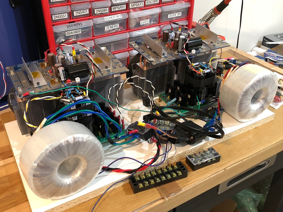
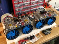
Oh, and for those not happy with my 1200pix wide images:

Starting to think about how to arrange it all on single melamine shelving plank for a dual monoblock stereo test. Wating for more ring crimp connectors and 16ga stranded 300vdc hookup wire to arrive before being able to connect everything. I am even adding a DC blocker to the mains input.
Front:
Back:
Oh, and for those not happy with my 1200pix wide images:
Attachments

Last edited:
Hi X,
Looking pretty cool...or is "rad" the more fashionable expression? 🙂
I for one am in favor of higher res pictures - much easier to distinguish details... looks better too. 🙂
Looking pretty cool...or is "rad" the more fashionable expression? 🙂
I for one am in favor of higher res pictures - much easier to distinguish details... looks better too. 🙂
Hi X, Hugh,
I think that the schematic for 1.35amp bias current in post 1500 has a value of the CCS fb resistor R128 that is not optimal.
The current swing of the CCS and the output transistor are out of balance.
Instead of 680R it should be 900R for equal currents, see ltpsice screenshots.
Regards,
Danny
I think that the schematic for 1.35amp bias current in post 1500 has a value of the CCS fb resistor R128 that is not optimal.
The current swing of the CCS and the output transistor are out of balance.
Instead of 680R it should be 900R for equal currents, see ltpsice screenshots.
Regards,
Danny
Attachments
Last edited:
The goal is to actually have the current in the Aleph sense resistor 2x the current in the CCS resistor - that produces the most efficient output power and deepest clip. The way to check is to set R132 to about 1/2 of R131 then apply AC modulation and measure the rms voltage across R131 and R132 AF they should be about equal in voltage, which means R132 is flowing 2x the current. Proper setting of R128, partially sets this optimal balance point.
Last edited:
Danny and X,
You are both correct.
But it is not straightforward.
There is some benefit in adding the active CCS resistor (I think it is R132?) as low as possible because all the load current is wasted in it. In the event of 3A, for example, with 0.18R we have a loss of 0.54V. The signal dropped across this resistor is then impressed through R128 to the base of the CCS controlling transistor, so it has to be adjusted to ensure that the dynamic range of both output devices is equal, as you have in your second graph, Danny. But if R132 is reduced to the specified 0.12, at 3A we only drop 0.36V across it, and correspondingly we need to reduce R128 to ensure equal current range in the two output devices.
When you read Nelson's comment on this, he describes a subtle change in the THD for unequal dynamic currents in the outputs. He suggests you can change R128 to select the optimal value; I have chosen to keep them equal, ensuring that outputs start to switch off identically at a higher value; he seems to believe that it is better if one output has around half the dynamic range than the other but believes it is personal choice. It is easy to do this on LTSpice; simply samples the currents in the sources. But in reality it's tricky because the pmos has not source resistor on it, so it might be convenient to put in a 0.1R source resistor on the pmos and then compare the current swings simultaneously.
I think your figures are current, Danny. As you change R132 and the quiescent this bi-swing changes quite a bit.
Actually, on the 20W Alpha, I suggest slightly more current, I like 1.46A, which using a nominal Vbe of 660mV on the controlling CCS transistor, corresponds to 0.44R. This accommodates speakers which dip down to 6R at peaks, which is more suitable for most speakers with complex crossover and mechanical configurations. I break this down to two 0.22R resistors, each rated at 2W, in series. Equal current swings come in at R128 520R. Both outputs start to bottom off at 19.1W output into 8R and 6R, which is about as good as it gets. This is -17.5V trough point.
Thanks for the input!
Hugh
I will stay with AB power amp at 1A bias with 40dc rails it just makes more sence for me. Of course it is not this circuit. 26years ago I did my first mosfet car amplifier at age of 17. Vertical Mosfets witch lasts for 20years are rare or the use is.Danny and X,
You are both correct.
But it is not straightforward.
There is some benefit in adding the active CCS resistor (I think it is R132?) as low as possible because all the load current is wasted in it. In the event of 3A, for example, with 0.18R we have a loss of 0.54V. The signal dropped across this resistor is then impressed through R128 to the base of the CCS controlling transistor, so it has to be adjusted to ensure that the dynamic range of both output devices is equal, as you have in your second graph, Danny. But if R132 is reduced to the specified 0.12, at 3A we only drop 0.36V across it, and correspondingly we need to reduce R128 to ensure equal current range in the two output devices.
When you read Nelson's comment on this, he describes a subtle change in the THD for unequal dynamic currents in the outputs. He suggests you can change R128 to select the optimal value; I have chosen to keep them equal, ensuring that outputs start to switch off identically at a higher value; he seems to believe that it is better if one output has around half the dynamic range than the other but believes it is personal choice. It is easy to do this on LTSpice; simply samples the currents in the sources. But in reality it's tricky because the pmos has not source resistor on it, so it might be convenient to put in a 0.1R source resistor on the pmos and then compare the current swings simultaneously.
I think your figures are current, Danny. As you change R132 and the quiescent this bi-swing changes quite a bit.
Actually, on the 20W Alpha, I suggest slightly more current, I like 1.46A, which using a nominal Vbe of 660mV on the controlling CCS transistor, corresponds to 0.44R. This accommodates speakers which dip down to 6R at peaks, which is more suitable for most speakers with complex crossover and mechanical configurations. I break this down to two 0.22R resistors, each rated at 2W, in series. Equal current swings come in at R128 520R. Both outputs start to bottom off at 19.1W output into 8R and 6R, which is about as good as it gets. This is -17.5V trough point.
Thanks for the input!
Hugh
I might have to try the 0.44R mod with the R128 at 520R. My Alpha 20 heatsink is only running 40C.
As opposed to B.B. at 37C at the mosfet body.
As opposed to B.B. at 37C at the mosfet body.
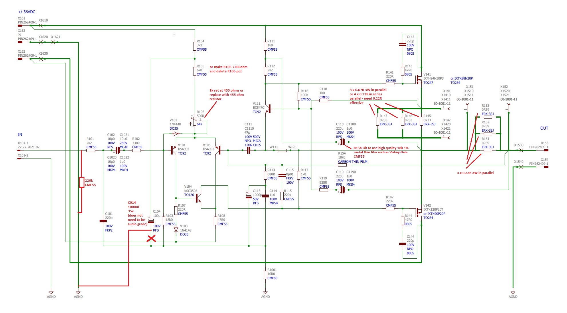
Here is the revised schematic for the Alpha BB. Waiting for concurrence of changes by Aksa.
Hey X,
What is the function of 220k resistor at the input? I missed that alteration.
Last edited:
It’s to reduce noise pickup when the inputs are not connected to a source. Did not seem to be an issue on Alpha 20 but B.B. PCB is larger and picks up more stuff.
Gotcha, makes sense now.
The ALPHA20 1.46A mod requires R131 value of 0.44R and R128 value of 520R, but R132 stays at 0.22R...Correct?
The ALPHA20 1.46A mod requires R131 value of 0.44R and R128 value of 520R, but R132 stays at 0.22R...Correct?
Gotcha, makes sense now.
The ALPHA20 1.46A mod requires R131 value of 0.44R and R128 value of 520R, but R132 stays at 0.22R...Correct?
I believe so, Hugh can confirm. I know Hugh likes R132 as low as possible - but according to the Pass article should be about half of R131.
I might have to try the 0.44R mod with the R128 at 520R. My Alpha 20 heatsink is only running 40C.
As opposed to B.B. at 37C at the mosfet body.
After you test this please share your opinion and the final schematic may upgrade the BOM if you have one
I still wait for the KSC1845 and BC547C to arrive.
Now you just upgraded the 47uF to 1000uF I need to reorder that also. I order my caps from S Korea, (Fine Gold & Sillmic) and it takes a couple weeks until arrives.
All do Huge wrote it does not need to be AUDIO quality - I would hate to put a cheap capacitor on these high-quality PC board and between the other boutique caps.
After I order the resistors, I mean that is the last to order.
By the way, can you measure the V on the C103 maybe I can use 16V type - you know not much room there for a 1000uF 25V. Thank you!🙂
Last edited:
I can't disagree with Pass, but to add to his comment I try to make R132 as low as possible. There are different designations on the ALPHA so I call it the load current sense resistor so there is no doubt about what it is. JPS changed my original designations, so there are times when I'm not sure what's meant here, particularly as they figures are very small and the picture needs to be magnified. Not a criticism but describing what the component does is useful because the entire commentary can then stand alone.
Vunce, the 220k references the input side of the coupling cap to ground, scotches hum when nothing is playing, and permit interconnection without thumps during switched on.
Hugh
Vunce, the 220k references the input side of the coupling cap to ground, scotches hum when nothing is playing, and permit interconnection without thumps during switched on.
Hugh
- Home
- Amplifiers
- Solid State
- Aksa Lender P-MOS Hybrid Aleph (ALPHA) Amplifier