Hi Hugh,
The idea of the FB divider is from you.
For 4R speakers I also wanted a DF of around 50, DF 4R = 1/2 DF 8R,
so this little trick does it.
This schema will be the Alpha20 I'll built:
- 4R compatible: 1.94A bias + FB shunt resistor of 1.8K
- ground lift for the input signal
- FB divider 50R-50R to double the damping factor
I almost got all the parts just one little last order 🙂
Regards,
Danny
Last edited:
A quick question regarding the power supply. I have a spare 0-22v 6.8A trafo and with Juma's cap multiplier boards I get a stable +/-28.1vdc output without any load. Is this more than the required voltage to power a 20w Alpha board with IRFP240/9240? I see that 0-18v with 25vdc is more common usage for this amp.
A quick question regarding the power supply. I have a spare 0-22v 6.8A trafo and with Juma's cap multiplier boards I get a stable +/-28.1vdc output without any load.
When your power supply is loaded with the Alpha20 it will drop a few volts and will be just right 🙂
Even if you had the full 28vdc you’d be fine, just make sure your heatsinking is able to handle the slight increase in power.
When your power supply is loaded with the Alpha20 it will drop a few volts and will be just right 🙂
Even if you had the full 28vdc you’d be fine, just make sure your heatsinking is able to handle the slight increase in power.
Thank you 🙂
I just received a new batch of Alpha 20 PCBs, in case anyone was looking to try it. They recently ran out of stock in my shop. A great amp to pair with the new SLB power supply.
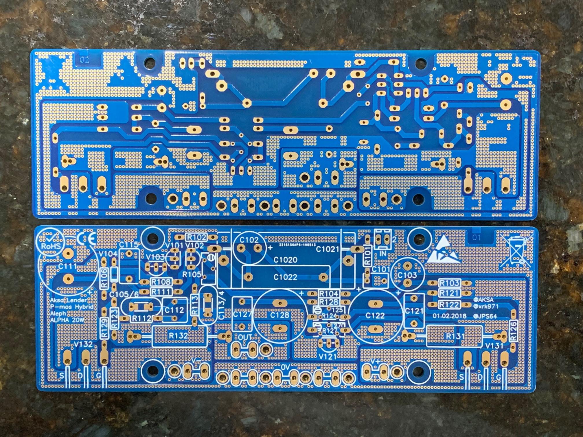
I just received a new batch of Alpha 20 PCBs, in case anyone was looking to try it.
Very good DIY Class A project, even for beginners. 🙂
What are the changes between the 4 and 8 ohm versions?
Can the IXTK88N30P pairs used with an 8 ohm bias?
Can the IXTK88N30P pairs used with an 8 ohm bias?
Last edited:
Thank you, that does explain the different R and C values between the two (post #1652 gave more detail). However I still don't understand what the difference between the IXYS and IRFP fets. Can the IXYS fets be used with an 8R setup with the lower bias current?
IXYS can handle more power and can be used at lower power and current like 8R but sort of a waste as they are about 10x the price of an IRFP.
Alpha 20 BOM?
Could one of you guys that have built the Alpha 20 and tweaked and modded parts could you revise the bill of material that is in post #510?
Because it looks like there were quiet a few changes especially
On resistor values.
Could one of you guys that have built the Alpha 20 and tweaked and modded parts could you revise the bill of material that is in post #510?
Because it looks like there were quiet a few changes especially
On resistor values.
Bigaudioscotto,
If you are building the Alpha, best to look at the GB and build thread here many of your questions will be answered.
Aksa Lender P-mos Hybrid Aleph (ALPHA) Class A Amp GB
But if you look at the last 2 entries on Post 1 of this thread you will see a definitive schematic diagram of the 4ohm version.
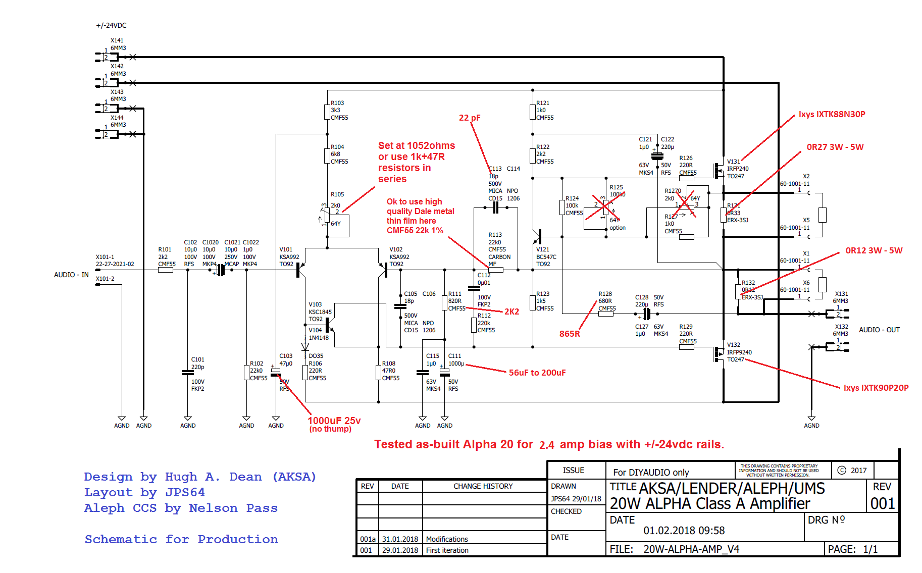
You might consider making that version as it works both at 4ohms and 8ohms and will give you a bit more power since you are starting from scratch with a trafo selection even. +/-27v would not be too much more heat and give you close to 32w I think - a significant improvement in headroom for driving something like a Manzanita.
If you are building the Alpha, best to look at the GB and build thread here many of your questions will be answered.
Aksa Lender P-mos Hybrid Aleph (ALPHA) Class A Amp GB
But if you look at the last 2 entries on Post 1 of this thread you will see a definitive schematic diagram of the 4ohm version.
You might consider making that version as it works both at 4ohms and 8ohms and will give you a bit more power since you are starting from scratch with a trafo selection even. +/-27v would not be too much more heat and give you close to 32w I think - a significant improvement in headroom for driving something like a Manzanita.
Last edited:
BAS,
I will be very happy to answer your questions; you can direct them to aspen01 -at- optusnet.com.au. Do please study the entire thread so you know the entire history of the project, it will be much easier to put things into perspective, particularly when you throw the switch.
Hugh
I will be very happy to answer your questions; you can direct them to aspen01 -at- optusnet.com.au. Do please study the entire thread so you know the entire history of the project, it will be much easier to put things into perspective, particularly when you throw the switch.
Hugh
Thanks Hugh,
I will try and get a better understanding of the whole
Project and try and go deeper in the threads to learn more
X has taught me what I know to this point he is a great guy,but this is still pretty foreign to me. I am a tube guy,so it is kind of teaching an old dog a new trick.
Anyway thanks for all your wisdom and expertise.
Scott
BAS,
I will be very happy to answer your questions; you can direct them to aspen01 -at- optusnet.com.au. Do please study the entire thread so you know the entire history of the project, it will be much easier to put things into perspective, particularly when you throw the switch.
Hugh
I recently purchased a PCB and the bom for the 4R version from a fellow builder. It makes sense to build the 4R version for the extra headroom, however I believe that setup requires cooling fans when installed in a 4U deluxe chassis. If cooling fans are indeed needed where is the best location to install them?
- Home
- Amplifiers
- Solid State
- Aksa Lender P-MOS Hybrid Aleph (ALPHA) Amplifier