Danny, Hugh, XRK:
Thank you all!
So in summary for 1.96A bias and overall 20dB gain:
1. Use the schematic in post 2781
2. Change R131 to 0.33 ohms
3. Change R128 to 680 to 700 ohms (closer to 700 preferred)
4. Keep R132 at 0.12 ohms
5. Change R111 to 2.5K or 2.7K ohms.
This should work nicely with my 96 dB efficient speakers that have an impedance nadir of 4.8-4.9 ohms.
Best,
Anand.
Anand,
How's the build going?
Danny, Hugh, XRK:
Thank you all!
So in summary for 1.96A bias and overall 20dB gain:
1. Use the schematic in post 2781
2. Change R131 to 0.33 ohms
3. Change R128 to 680 to 700 ohms (closer to 700 preferred)
4. Keep R132 at 0.12 ohms
5. Change R111 to 2.5K or 2.7K ohms.
This should work nicely with my 96 dB efficient speakers that have an impedance nadir of 4.8-4.9 ohms.🙂
Best,
Anand.
Ltspice lack of worst case analyses of BOM ,parasitic elements, exluding thermal domain analyses of a class A push pull amp .
Good luck anand . Hugh might confirm
VERILOG-A SUPPORT OPTION
SimElectronics models
Saber supports spice files of extensions .mod, .cir, .ckt, .spi, .lib.
Use of The System Designer’s Guide to VHDL-AMS
Further analyze
parametric sweep, sensitivity, statistical, and
worst case analyses of BOM inc."(time-dependent
current-density functional theory) combined with quantum electrodynamics"
Direct access to transient regimes, to how the
steady state is approached, and to whether or not this steady
state is unique or depends on the history of the system .also transient analysis (power on) mechanical,extended test other domanins than frequency domain..tr0/.mt0,
.psf, .fsdb, and .wdf output formats too see stabile simulation what happens if extremes in component tolerances in a worst-case system scenario of Alpha20 or B.B BOM
The use of Monte Carlo and Worst Case analyses along with statistical tools
helps the engineer predict how the circuit will behave after it has been
manufactured and helps to ensure the maximum production yield.


Enjoy simulations and optimizations. 😎
Hi fellas,
I’m in SFO for a few days to attend the Burning Amp festivities. 😉
I’ve ordered parts for the above so it will have to wait till I come back...and several weekends I am sure!
Best,
Anand.
I’m in SFO for a few days to attend the Burning Amp festivities. 😉
I’ve ordered parts for the above so it will have to wait till I come back...and several weekends I am sure!
Best,
Anand.
Hi fellas,
I’m in SFO for a few days to attend the Burning Amp festivities. 😉
Enjoy 🙂
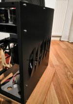
Those “shark gill” slits look very cool. As long as it lets air in without turbulence or whistling then it’s good.
Those “shark gill” slits look very cool. As long as it lets air in without turbulence or whistling then it’s good.
Yes it does, had to run test just few moments ago. Just as quiet as square hole. Case lets hot air flow through the roof as well, capacitor deck is open from front and rear. Also glass roof is rised few millimeters.

Very nice job, Juntuin!

Thanks X! Painting went quite wrong again, but this is DIY!
Hello,
I'm in the process of gathering parts to build a pair of the BB's. I have a couple of questions that I hope someone can answer:
I've noticed a mixed bag of PS filters. I'd planned on using the DYIA universal PS board.
Is that not enough?
What additional filter caps will I need? Recommended sizes?
Is there a consensus on what size transformer is needed for each channel? I was planning to purchase a pair of Antek 400VA 30v fmrs.
Any advice would be appreciated.
Thanks,
Steve
Is there a consensus on what size transformer is needed for each channel? I was planning to purchase a pair of Antek 400VA 30v fmrs.
Any advice would be appreciated.
Thanks,
Steve
Hi Steve,
30v secondaries would work really nice, maybe step up to 5-600va per channel though.
Hi X
What do you think about if I convert the 20W to a BB with a passive heatsink. I plan to make or buy a long output PC board so I can use 2pair power mosfet (the large ones,) or 3 pairs from the smaller ones per channel. I think I will go with the second option because I have a couple pair of those already. If you remember I sent pictures from my heatsinks 15" tall monster. That amplifier case was originally designed for an Aleph2 100W amplifier. I have to reread the thread to see if someone at least run some simulation at that option. I have some giant transformers 2x30V 1000VA or 2x28V 800VA. One will be used to a Krell KSA 50+. I want to know your opinion. Air cooling to me, not an option! I'd rather not build that to go to use active cooling. Next week will fish out my heatsink under the pile of my DIY stuff and old commercial amplifier, so I can post a picture. I know that heatsink more than capable to handle a 50W Class A amplifier. I want to know your opinion, please. Greetings gabor
What do you think about if I convert the 20W to a BB with a passive heatsink. I plan to make or buy a long output PC board so I can use 2pair power mosfet (the large ones,) or 3 pairs from the smaller ones per channel. I think I will go with the second option because I have a couple pair of those already. If you remember I sent pictures from my heatsinks 15" tall monster. That amplifier case was originally designed for an Aleph2 100W amplifier. I have to reread the thread to see if someone at least run some simulation at that option. I have some giant transformers 2x30V 1000VA or 2x28V 800VA. One will be used to a Krell KSA 50+. I want to know your opinion. Air cooling to me, not an option! I'd rather not build that to go to use active cooling. Next week will fish out my heatsink under the pile of my DIY stuff and old commercial amplifier, so I can post a picture. I know that heatsink more than capable to handle a 50W Class A amplifier. I want to know your opinion, please. Greetings gabor
Gaborbela,
I think that that can work as 3 pairs is 33w per pair of dissipation is within the safe operating limits of IRFP9240/240. Just modify circuit to use values of the 55w B.B.
Good luck!
X
I think that that can work as 3 pairs is 33w per pair of dissipation is within the safe operating limits of IRFP9240/240. Just modify circuit to use values of the 55w B.B.
Good luck!
X
Gab,
I confer entirely with X, and add one issue: current sharing with the output pairs. You should try to match the transconductance and the Vgs at around 800mA for the three IRFP240, and then matching IRFP9240 separately again. They do not need to match with each other, nmos and pmos, but within their category they must be matched. Getting both parameters is always difficult, so with 40 IRFs you should get three matched of each gender.
The difficulty of matching mosfets is the reason we use very large, high dissipation mosfets. With these IXYS devices, you have so much capacity you do not need to match pairs, which is a great advantage.
Ciao,
Hugh
Gab,
The difficulty of matching mosfets is the reason we use very large, high dissipation mosfets. With these IXYS devices, you have so much capacity you do not need to match pairs, which is a great advantage.
Ciao,
Hugh
Thank you Hugh
Unfortunately, that is NOT an option for me to test the BB.
 😱
😱One par mosfet cannot be cooled with a passive heatsink, I will put this project on hold until spring.
I have several other projects to work on it.
Greetings gabor
Yes, Hugh is absolutely making an important point about matching within the same sex MOSFET, as an imbalance will send one to dissipate more than the safe operating limits and it will fry, which subsequently places unsafe currents on the next and they will fry - a chain reaction that will wipe out all outputs in a matter of maybe 10 seconds.
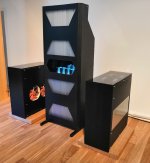
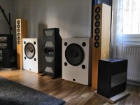
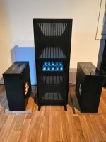
Made X a promise earlier that I'll post some family photos with Alpha20 and B. B.
Very cool Juntuin... Class A all the way!
- Home
- Amplifiers
- Solid State
- Aksa Lender P-MOS Hybrid Aleph (ALPHA) Amplifier