The 1uF has been in series with another cap though up to this point which would mask any issue with DC leakage... OK its very unlikely but don't totally discount it.
It could be a transistor. Make sure there is no 'conductive' gunge or flux around where you have been working too.
Think I've narrowed the fault down Mooly, thanks to the high-tech artists paint-brush prodding technique (tm) 😉
Strangely, the slightest touch on either of the shielded signal cables which connect the tone control board to the amplifier PCB alters the rustle, including causing some in the right channel too. I have triple checked for any tiny stray wires or flux conducting issues but cannot see anything obvious (and it was working fine before). Could these shielded signal carrying wires be acting as some kind of noise 'antennae' that are fine ordinarily with the 2.2uf caps one end, the 1uF at the other, but have issues with the 2.2uFs linked out at the source end?
Will investigate further...
I wouldn't have thought the wiring would do that when its still and fixed (shielded cable can produce audible noise when connected to a high gain amp and when the cable is moved and physically distorted... but not here)
Try removing the cap connected to C1 collector above which isolates one stage from the other and see if the noise goes. That splits the preamp board in two.
Are you sure those switches and pots are OK. Give them all a good workout.
Try removing the cap connected to C1 collector above which isolates one stage from the other and see if the noise goes. That splits the preamp board in two.
Are you sure those switches and pots are OK. Give them all a good workout.
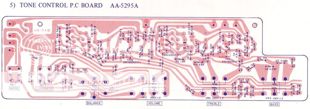
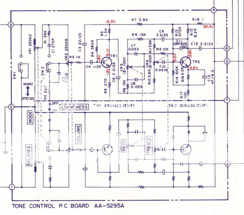
Do you mean remove the coupling cap C6, per channel, that's attached to the collector of TR1?
I'm wondering if it's the cable used? I had to replace the original stuff, and used Van Damme XKE instrument cable, which has been fine whenever I used it in the past. The lightest touch on either does cause rustling sounds in the respective channel. Double-checked the wiring & soldering, both are very neat & secure. Recleaned the surrounding areas with isopropyl but no change.
At this point I'm actually tempted to put it back to how it was when stock Mooly. I'm sure now the problem is linked between either the removal & linking of the 2.2uF positions, or the removal of those 100K resistors on the main board, and interaction with the cable. Either way the interconnect seems to be acting in a very microphonic way now.
P.S. Switches & pots were given a shot of Servisol cleaner a few weeks back, and turned backwards and forwards several times. Never had a problem with them to be honest.
Its probably quicker to revert it back as a quick proof or otherwise. Its only a couple of minutes work.
Cable is silent when its not being moved, and I think you could hear the problem in normal listening.
Removing C6 breaks the signal path. If the rustling is gone then its a problem before that point. Same applies to C4.
Cable is silent when its not being moved, and I think you could hear the problem in normal listening.
Removing C6 breaks the signal path. If the rustling is gone then its a problem before that point. Same applies to C4.
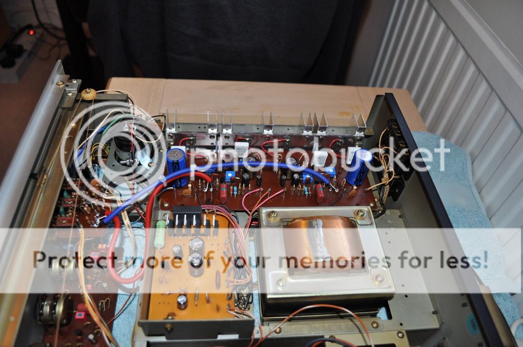
Have restored it back to stock and it's all working fine again now, albeit with a slight rise in the noise floor due to that extra pcb stage (visible on the left side of the shielded red & blue wires below) and the added effects of carbon film resistors and a switch or two? But no rustling anymore, so I'll leave it there now 😉

Thanks for your help once again Mooly, and to everyone else who commented.
Time to pour a cider & crank up the volume! 🙂
John
Thanks for your help once again Mooly, and to everyone else who commented.
Time to pour a cider & crank up the volume! 🙂
John
Time to pour a cider & crank up the volume! 🙂
John
That's more like it 😉
Seriously though... its great you have it working but its a darned curious problem. The 100k to ground from the junction of the two caps shouldn't really have any bearing on this and yet I wonder...
Two things I would try just for my own curiosity if it were mine.
Supposing you link out the cap again and remove the resistor. The noise is present. You could add the 100k and a series cap as an additional load to ground from the collector of that last transistor in the preamp. That's just crazy though...
And the other suggestion. Try different caps at the input of the power amp. Use an electrolytic if needs be as a test but remember the polarity will now be reversed because the collector of the preamp stage is at a higher voltage than the power amp input.
I think it's probably best leaving it as it is now. I don't want to risk upsetting anything again or risk getting to the lifting solder pads stage (knowing how fragile they usually are in amps of this era). Plus a sciatic nerve & back problem means it's a literal pain to work with - 'tis a heavy bugger.
What I am going to do is get the bulbs replaced with an led strip for even lighting of the display windows. And I think it might be an idea to get that diode bias attangement replaced with a vbe. I haven't a clue how to go about doing that but will get Googling 😉
In the meantime I'm just going to enjoy the music. Ironically there was a (very) slight rustle from the right speaker when I turned it on today. Turns out this time it's those high/low switches which were wired back in yesterday. Might need to give them another shot of switch cleaner. But other than that very brief noise, appears to be fine again 🙂
Fair enough 🙂
The books of Doug Self would be a good place to read up on (the details) of Vbe multipliers and the ideal theoretical bias currents for a given output stage. The first job is to figure out a way of attaching a suitable transistor to the heatsink or preferably to have it in contact with one of the output devices. The actual transistor used depends really on that question. A small T092 type or a T0126 type, all are electrically suitable.
This thread might give you ideas. Here is how I did it:
http://www.diyaudio.com/forums/soli...t-top-body-output-transistor.html#post1429206
I like the phosphor spring idea Mooly - very neat and I assume very effective too. I'll have a proper read through that thread shortly, ta.
I also found this PDF which looks promising:
http://www.hagtech.com/pdf/vbe.pdf
I also found this PDF which looks promising:
http://www.hagtech.com/pdf/vbe.pdf
Interesting.
The vbe multiplier has been around since the early days of transistor amps but it seems only in recent years that we have started refining them quite so much.
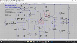
Something like Doug Selfs arrangement on his 'Blameless Class B' design would be very suitable I would have thought.
This is the arrangement. The 297ohm would be the preset and the 16 ohm might be slightly tweakable to get the very best result in your amp. Best as in least change with temperature.
The vbe multiplier has been around since the early days of transistor amps but it seems only in recent years that we have started refining them quite so much.
Something like Doug Selfs arrangement on his 'Blameless Class B' design would be very suitable I would have thought.
This is the arrangement. The 297ohm would be the preset and the 16 ohm might be slightly tweakable to get the very best result in your amp. Best as in least change with temperature.
Attachments
Thanks for that Mooly. I need to read up on how to apply this before I consider attempting it. It'd have to be a physically neat solution too which I could easily fit in place of the current VD1222 substitutes (series connected pairs of 1N4148s).
Also need to track down yet something else. Getting a rustling sound from the right speaker only now, when I first switch the amp on, similar to the sound one often gets from turning a crackly volume pot. But right channel only. It only lasts for around 3 seconds and isn't particularly loud. I don't think its anything to do with the previous 'rustling interconnects' issue before. The amp did this when I first bought it actually, prior to a recap (which had appeared to cure it). As all I've done is wire that small high/low on/off filter pcb back in so the amp is stock again, I feel it's to do with that. Possibly switch related - corroded contacts perhaps. A hard issue to catch as it's only during turn on. So momentary current surge related perhaps?
It's sounding so good now, I had to curse when I heard that sound on switching on! I may consider hiring an audiophile priest to exorcise this amp 😉
Last edited:
Switches and pots are the most likely problem areas. If you get nowhere then just keep splitting the audio chain until the problem disappears. Also see if the noise is affected by the volume control and also the tone control settings.
The vbe multiplier should be easy to configure. Just mount the transistor on the heatsink and wire C and E to the appropriate points on the PCB. Replace the trimmer with the chosen new value and wire the appropriate end to the base of the new transistor. Remove the diode chain and in their place add the chosen fixed resistor that will go across C and B of the new transistor.
So nothing has been hacked about or altered on the board.

Thanks Mooly - looks very simple to install, and would be of benefit performance wise so seems like a no brainer.
So replace VR2 (200R trimmer) with a 297R resistor (or thereabouts) instead.
VR1 (30K) elsewhere in circuit kept as-is.
VD1222 replaced with approx. 16R. How to fine tune that value? Can it be calculated 'on paper' or would it be best to replace with a trimmer?
So replace VR2 (200R trimmer) with a 297R resistor (or thereabouts) instead.
VR1 (30K) elsewhere in circuit kept as-is.
VD1222 replaced with approx. 16R. How to fine tune that value? Can it be calculated 'on paper' or would it be best to replace with a trimmer?
I was doing it without the 16 ohm tbh. Just a very simple multiplier in the time honoured fashion that we used for years. If you wanted to add the resistor then it would be less disruptive to place it at the multiplier itself. That way all the print stays original, no cutting or hacking. With the multiplier on the heatsink there will always be some thermal inertia, if you can place it on (touching) one of the outputs then you would get better control. Its all relative though and we never used to fret over such things in the past.
VR2 stays a trimmer but would typically be a 470 or 500 ohm preset. The resistor from C to B on the multiplier would be around 1k. VR1 stays the same.
VR2 stays a trimmer but would typically be a 470 or 500 ohm preset. The resistor from C to B on the multiplier would be around 1k. VR1 stays the same.
Thanks for clarifying that resistor between C & B of the muliplier Mooly. So 1K for that then. Either on the pcb where the vd1222 was originally mounted, or between the legs of the multiplier itself then.
Any suggestions for the multiplier? Mr Self's diagram shows MJE350C. A good choice here?
Any suggestions for the multiplier? Mr Self's diagram shows MJE350C. A good choice here?
MJE340, the 350 is the PNP. Pretty much anything is OK for this because its not in the signal path as such. You would need to insulate it from the heatsink.
How are the diodes mounted ? Could you rig anything up there using a smaller package device.
How are the diodes mounted ? Could you rig anything up there using a smaller package device.
Just quickly rehashing the circuit above to match your quasi configuration and we get something like this. This is running at 50ma bias in the simulation. The 1k is probably going to need be nearer 820 ohms to get a suitable adjustment range with a 470 ohm preset.
For minimum bias current the transistor has to be fully on and that means the preset has to be at its highest value (470 ohm). That's the starting point. I'm wondering if its safer to go with a 1k preset. Although 470 ohms is OK in simulation, its a bit marginal in that it only just reduce the current to zero. Going to 1k would be more certain. If you went to 1k for the preset then the originally suggested 1k for the C-B resistor would be OK as well.
For minimum bias current the transistor has to be fully on and that means the preset has to be at its highest value (470 ohm). That's the starting point. I'm wondering if its safer to go with a 1k preset. Although 470 ohms is OK in simulation, its a bit marginal in that it only just reduce the current to zero. Going to 1k would be more certain. If you went to 1k for the preset then the originally suggested 1k for the C-B resistor would be OK as well.
Attachments

- Home
- Amplifiers
- Solid State
- Akai AA-1020 burning resistor woe!