I've never heard of cathode stripping in pass tubes, but I wouldn't be surprised if it were true. It's definitely a phenomenon in high voltage transmitting tubes though, which is one of several reasons broadcast transmitters employ a substantial filament heating period when beginning from a cold start. I discarded the idea of cathode stripping in regular audio amps 20 years ago when I acquired a 1930's Zeniith tombstone radio with its original 6L6G outputs intact. Today they're 80+ years old and still going strong.
As a novice builder I did get swept up (briefly) in a similar phenomenon - babying tube heaters. 18 or so years ago I built two amps from scratch using schematics from a popular magazine. Both used a three switch scheme that placed power resistors in series with the heaters. The idea was that you'd "preheat" the heaters when the first switch was thrown. The second switch shorted out the "preheat" resistor, then when all the tubes were a' glowin' you'd apply the B+ with the third. It was all pretty Rube Goldberg-esque and completely unnecessary of course, but it did sell magazines and get me infecte- er, started in this hobby.
Parenthetically, the first amp (a hoary old PP 6V6 Hafler/Dynaco circuit) sounded stunning, probably because of the old Heathkit iron I'd scavenged for the outputs. The second, however, was a SE 6550 job that was an utter turd on toast. Not wanting to hold my nose and nibble around the edges, I parted it out and didn't build another SE amp for 15 years. To this day it remains the only full-up build I've ever dismantled.
Today I just throw a CL-60/90/140 in between the fuse and the transformer primary and call it good. I'm too old to be looking for monsters under my bed, much less be afraid of them.
Last edited:

Hello here today.
Really nice explanation thanks... 🙂
This is also what happens when i power mine up, B- is there right up, making perfect sense now that i fully understand it.
That's what i have now (STM CL-60 + 800mA fuse ~230vac)... Now i will use 5 minutes for cleaning under my bed for thoose monsters 😱😎😀... Thanks all
Rgds; Jesper.
The warm up time of a 45 or 300B is still faster than a 5U4 since there is more thermal mass in the 5U4's filament. There are possibly some 2A3's out there that are slow, but this is not generally a problem.
Slowly turning up the input voltage on a Variac allows all supplies to come up at roughly the same time. The TSE and TSE-II use a tube rectifier for B+ and a solid state rectifier for B- to insure that excess negative bias is there BEFORE the output tubes are warm so that they are cutoff during the first few seconds of conduction. The B- stays pretty far negative until the B+ comes up and starts pulling the grid bias more positive.
Really nice explanation thanks... 🙂
This is also what happens when i power mine up, B- is there right up, making perfect sense now that i fully understand it.
Today I just throw a CL-60/90/140 in between the fuse and the transformer primary and call it good. I'm too old to be looking for monsters under my bed, much less be afraid of them.
That's what i have now (STM CL-60 + 800mA fuse ~230vac)... Now i will use 5 minutes for cleaning under my bed for thoose monsters 😱😎😀... Thanks all
Rgds; Jesper.
4 pin sockets
What have you guys used for 4 pin sockets? I haven't found any that are pc mount. Any suggestions?
What have you guys used for 4 pin sockets? I haven't found any that are pc mount. Any suggestions?
coopercustoms,
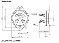
There is good info given by George on how to install the the 4 pin sockets on PCB towards the end of this web page:
Tube Sockets | Tubelab
Theses sockets might work too, but have no experience with them:
2PCS EIZZ Quality Ceramic 4pin Gold Plated U4A Tube Socket Audio Amplifier For 300B 2A3 811 572B 5U4G 6B4G 274A 866 PX4-in Amplifier from Consumer Electronics on AliExpress
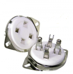
My suggestion would be to not use PC mount. But get normal ones. Fit the normal ones to the chassis plate and wire it to to the pcb with wires. I just hate the idea (despite many that have never had a problem with it) to push and pull something soldered to a pcb.What have you guys used for 4 pin sockets? I haven't found any that are pc mount. Any suggestions?
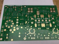
I used the "normal ones", bent the pins and soldered to the PCB as in George's tutorial and screwed the tabs to the top plate. There is no stress on the PCB this way
Attachments
Last edited:
I used the "normal ones", bent the pins and soldered to the PCB as in George's tutorial and screwed the tabs to the top plate. There is no stress on the PCB this way

Last edited:
coopercustoms,
There is good info given by George on how to install the the 4 pin sockets on PCB towards the end of this web page:
I used the "normal ones", bent the pins and soldered to the PCB as in George's tutorial and screwed the tabs to the top plate. There is no stress on the PCB this way
Same thing as these:
Attachments
Does anyone have a Front Panel Express file for the TSE-II they'd be willing to share? I'm struggling to build one of my own using the program.
Here is one that should help you get started.
You'll have to adjust the holes for the transformers, and the PCB standoffs if you dont want to use the ones I did.
This one also has holes for mounting the 4-pin tube sockets to the chassis.
You'll have to adjust the holes for the transformers, and the PCB standoffs if you dont want to use the ones I did.
This one also has holes for mounting the 4-pin tube sockets to the chassis.
Attachments

Here is one that should help you get started.
You'll have to adjust the holes for the transformers, and the PCB standoffs if you dont want to use the ones I did.
This one also has holes for mounting the 4-pin tube sockets to the chassis.
This is super helpful -- thanks! What PCB standoffs did you use?
What PCB standoffs did you use?
I used these M4, 16mm length as they matched the height of the 4-pin socket tabs.
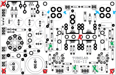
The attached picture corresponds to the holes around the PCB in the FPD layout. The red marks are where I used standoffs, green are the holes for the pot adjustment, and blue is where I secured the 4-pin socket tabs.
If your 4-pin socket dont have mounts for screws, then I would also use the 2 standoffs right above them
Attachments
- Home
- More Vendors...
- Tubelab
- After a 14 year run, the TSE must DIE!