Hey Guys,
I have been busy with exams so haven't had any time for projects.
I've done some mucking around on boxsim and have found a way to match the phase better (at least I think its better) by using a 4th order filter for the tweeter with the tweeters polarity reversed.
Is this any better than my previous attempts?
Also should the impedance response be flat or is this alright?
Thanks, Jeremy
I have been busy with exams so haven't had any time for projects.
I've done some mucking around on boxsim and have found a way to match the phase better (at least I think its better) by using a 4th order filter for the tweeter with the tweeters polarity reversed.
An externally hosted image should be here but it was not working when we last tested it.
An externally hosted image should be here but it was not working when we last tested it.
An externally hosted image should be here but it was not working when we last tested it.
Is this any better than my previous attempts?
Also should the impedance response be flat or is this alright?
Thanks, Jeremy
I think your notch is too high and too deep on the 5" fullranger. Should be around 7kHz with about 33R. That should straighten out phase.
Your Vifa 1" metal tweeter attenuator should be about 4.7R and 4.7R. Always go for standard values if you can.
Every time I look at this one, I get a second order tweeter. 3.3uF and 0.3mH is standard 3kHz stuff, but a 10uF does no harm if you want it brighter at crossover.
All very safe on impedance anyway.
Attachments
Steve,
Yes, OP has it dampen between 2k-5k. It doesn't seem right. The most important above mid frequencies. I would give both xovers a chance.
Yes, OP has it dampen between 2k-5k. It doesn't seem right. The most important above mid frequencies. I would give both xovers a chance.
Hi Guys,
I never seem to get the phase right for the tweeter with a 2nd order filter. The slope is never steep enough on the right side.
This is with your crossover (Steve)
I used your advice about the 33 ohm resistor and that has seemed to improve the phase.
How does this look?
Do you guys think there is something wrong with the frd and zma files I am using?
Thanks, Jeremy
I never seem to get the phase right for the tweeter with a 2nd order filter. The slope is never steep enough on the right side.
This is with your crossover (Steve)
An externally hosted image should be here but it was not working when we last tested it.
I used your advice about the 33 ohm resistor and that has seemed to improve the phase.
An externally hosted image should be here but it was not working when we last tested it.
An externally hosted image should be here but it was not working when we last tested it.
An externally hosted image should be here but it was not working when we last tested it.
How does this look?
Do you guys think there is something wrong with the frd and zma files I am using?
Thanks, Jeremy
This for the second order idea:
That to me looks like the tweeter needs to go back about 15mm as point of sound origin SEO in boxsim driver2. driver1, the bass should be roughly 30mm.
Your attenuator is wildly wrong too. It should come out as a 6-9 ohm load for the filter. Try 4.7R in both legs.
An externally hosted image should be here but it was not working when we last tested it.
That to me looks like the tweeter needs to go back about 15mm as point of sound origin SEO in boxsim driver2. driver1, the bass should be roughly 30mm.
An externally hosted image should be here but it was not working when we last tested it.
Your attenuator is wildly wrong too. It should come out as a 6-9 ohm load for the filter. Try 4.7R in both legs.
If you want to see the phase take on the same shape you might look at mirroring the shape of the response from each driver.
Direct on axis measurements especially.
Probably. A single on axis plot is not likely to be a precise representation of what the speaker will be doing, especially at the band extremes.Do you guys think there is something wrong with the frd and zma files I am using?
Direct on axis measurements especially.
For the SEO I have set the tweeter at 2 mm and the woofer at 35mm behind the baffle. These are measurements I have roughly taken with a ruler (from where dust-cap meets cone to the top of the frame. I had planned to have a baffle with the two drivers recessed flush with the wood. Is this the correct way to measure SEO? Wouldn't a 15mm SEO for the tweeter mean a stepped baffle?
I will redo the frd and zma files tomorrow.
Also, for the attenuation I let boxsim optimise the original values I had entered. I don't really understand why the attenuation is wrong, could you please explain that to me 😛.
Thanks, Jeremy
I will redo the frd and zma files tomorrow.
Also, for the attenuation I let boxsim optimise the original values I had entered. I don't really understand why the attenuation is wrong, could you please explain that to me 😛.
Thanks, Jeremy
Mate, the SEO is nearer the voicecoil. But just set up a project and load a few tweeters. You'll find the SEO is always between 12mm and 18mm. End of.
And FWIW, Boxsim considers any impedance above 4 ohms as job done. It's clueless about attenuators, impedance and filter load. Like you.
So try it my way. And if you don't like it, THEN try it your way. Sorry to rant.
And FWIW, Boxsim considers any impedance above 4 ohms as job done. It's clueless about attenuators, impedance and filter load. Like you.
So try it my way. And if you don't like it, THEN try it your way. Sorry to rant.
Do you guys think there is something wrong with the frd and zma files I am using?
Jeremy,
Apparently you are using the old datasheet of the tweeter where the SPL is shown at 2V/0.5m. Consequently the tweeter level is augmented by 3 dB in all of your simulations. The latest datasheet uses standard measurement conditions (2.83V/1m) and avoids that issue: http://www.tymphany.com/wp-content/uploads/2014/11/Discontinued-Vifa-Products-D25AG-35-06.pdf
As mentioned before I cannot confirm your phase plots since I get different results. Perhaps it would be wise to redo the data files and to upload them afterwards for verification. And as a side effect, you could stop System7 from "crossover guessing" using wrong drivers. 😀
Ohh the SEO measured from around the voicecoil... 😛
That means that the SEO for the tweeter will be around 12mm and the woofer around 40mm (according to my measurements) which is within the range that you have set. 🙂
I have redone the frd and zma files for both drivers (using Zaph's graph for the woofer http://www.zaphaudio.com/5.5test/Tangband-W5-704D-FR.gif and the graph linked by Dissi). First I traced the frd and zma using spl copy. Then I normalised the data in spl view from 20hz to 20khz. Lastly I extracted the phase using Jeff Bagby's phase extractor. Is this the correct way to do it?
These are some images of the frd and zma graphs:
D25AG 35-06
704D
I will do some testing with the new SEO values today.
Thanks, Jeremy
That means that the SEO for the tweeter will be around 12mm and the woofer around 40mm (according to my measurements) which is within the range that you have set. 🙂
I have redone the frd and zma files for both drivers (using Zaph's graph for the woofer http://www.zaphaudio.com/5.5test/Tangband-W5-704D-FR.gif and the graph linked by Dissi). First I traced the frd and zma using spl copy. Then I normalised the data in spl view from 20hz to 20khz. Lastly I extracted the phase using Jeff Bagby's phase extractor. Is this the correct way to do it?
These are some images of the frd and zma graphs:
D25AG 35-06
An externally hosted image should be here but it was not working when we last tested it.
An externally hosted image should be here but it was not working when we last tested it.
704D
An externally hosted image should be here but it was not working when we last tested it.
An externally hosted image should be here but it was not working when we last tested it.
I will do some testing with the new SEO values today.
Thanks, Jeremy
Dissi can be a bit snarky to me sometimes. To be fair to him, he DOES get involved in detailed design more that most people here, who get a bit vague on detail after all the opinionating about LR4 and LR2 slopes an' all that. 🙂
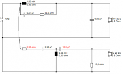
I don't know if you like a challenge, but Cousin Billy has invented a really good circuit IMO. It's a series XO design and it solves an awful lot of problems with parallel circuits. Seems to work rather well with 5" bass.
The red values are what IMO you could let boxsim optimise for your drivers. See how it looks. Phase is not ruler flat, but I don't think that matters to much.
You could use a cheap and small NP electrolytic for the 22uF. But IMO, this will sound very good indeed. As well as being very bleeding edge! 😎
Attachments
I hope my less than enthusiastic commentary on the Kimber circuit wasn't taken to heart there. I came across that one years ago. It is after all a differently motivated circuit.I don't know if you like a challenge, but Cousin Billy has invented a really good circuit IMO.
Hey Guys,
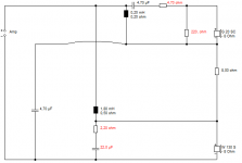
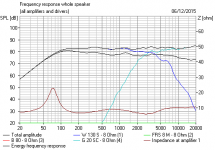
Here's how Cousin Billy's filter looks:
Phase isn't perfect but I don't think if will ever be 😛 . Cool design.
Thanks, Jeremy
Here's how Cousin Billy's filter looks:
An externally hosted image should be here but it was not working when we last tested it.
An externally hosted image should be here but it was not working when we last tested it.
An externally hosted image should be here but it was not working when we last tested it.
Phase isn't perfect but I don't think if will ever be 😛 . Cool design.
Thanks, Jeremy
Phase isn't perfect but I don't think if will ever be 😛
 Take it from me, (I obsess over small details) You are better off stopping at some point and just building it and seeing how it sounds! As long as there aren't gross problems with the phase (like being 45 deg out at crossover or close too it) it will probably be fine 🙂 It's fine to spend time optimising it, but at some point you have to call it a day.
 edit: once you do provided it sounds good, you will kick yourself for not doing it sooner 😉 My first speaker design took me 6 years (actually probably 7 if you count from when I started researching it as opposed to when I bought the drivers. A large part of the problem was I was scared to design the crossover, worying about how expensive the parts would be. In the end I built a simple crossover using low cost coils and caps just to get an idea of how it sounded. I used that for a year before I did a more serious design, which completely transformed them, but even with the first design the sound was much better than the old three ways that they replaced.
Tony.
Last edited:
If this crossover has no major problems with it, I think I'll take Tony's advice and just build it.
Thanks, Jeremy
An externally hosted image should be here but it was not working when we last tested it.
An externally hosted image should be here but it was not working when we last tested it.
An externally hosted image should be here but it was not working when we last tested it.
Thanks, Jeremy
Hi Jeremy, not withsanding the subsequent comments, I think that the phase of the crossover you posted in post 101 is better. This latest one whilst it lines up at high frequencies (where it is going to matter less) is not so good around the crossover frequency where out of phase will do the most damage... unless it is arounf 90 deg out of phase (typical for an odd order crossover) which is ok.
If you adress the comments on the notch (for post 101) which I admit I have not fully digested yet) you may be better off. Sorry to say that after my last post, but IMO this latest one is a regression... perhaps wait to see other comments as I may be off with the fairies 😀
Tony.
If you adress the comments on the notch (for post 101) which I admit I have not fully digested yet) you may be better off. Sorry to say that after my last post, but IMO this latest one is a regression... perhaps wait to see other comments as I may be off with the fairies 😀
Tony.
Is it the flattening response of the woofer from 3.2 to 3.6 KHz the issue?
Would this classify as uniform roll-off's?
Thanks, Jeremy
Would this classify as uniform roll-off's?
An externally hosted image should be here but it was not working when we last tested it.
An externally hosted image should be here but it was not working when we last tested it.
An externally hosted image should be here but it was not working when we last tested it.
Thanks, Jeremy
yes that is pretty much it 🙂 you ideally want something approximating a perfect 2nd, 3rd or 4th order slope without too much lumpiness or deviation. Both drivers should be doing this. You can get what looks to be a flat fr if one driver is lacking in an area where another is adding but that's not ideal... Invert one of the drivers and do a sim and see what the dip looks like. If it is lopsided or wide and shallow that's not so good.
Tony.
Tony.
- Status
- Not open for further replies.
- Home
- Loudspeakers
- Multi-Way
- Advice on bookshelf speaker build