I'll bet it nothing more than the asymmetric strength-of-pullup versus strength-of-pulldown. I'll bet it goes away when you change from switching between {0A, 0.53A} and instead switch between {0.2A, 0.73A}.
When the load switches off there's nothing at all to pull the output downward. Nothing is fighting against the regulator's pass transistor. So when the output overshoots that very first millivolt, the ONLY thing to bring it back down is the meager bias current thru the resitive divider that senses the output voltage. And maybe the delta-V across the electolytic's ESR. FURTHERMORE you're now running the pass transistor at ~zero current so its gm is ~zero so the regulator's feedback loop is operating in the uncharted territory of "comatose". Ick and pew.
Doctor it hurts when I do this. Don't do that.
If you had installed bleeder resistors across the output capacitors, would they have helped (marginally)? Yes they would.
5V transient testing done and I think a pass with good marks. I tested preloads of 0.63A, 1.25A, 2.5A, 3.75A and, finally, 2R||4R||8R for 4.4A, each with the 0.53A step. Here's a few pics of the 4.4A preload test.
I have 2x470u output caps installed. I have slots on the board for another three 3.5mm pitch output caps and have some 220u which would fit. I'm wondering if there is any downside to populating these (assuming component cost is a sunk one and is pence in any event).
PS: boy those 3x0.47R 3W power resistors get hot
Attachments


Last edited:
The downside is, you have to transient load test the whole shebang again. Increasing load capacitance right at the regulator output, moves the output pole to a lower frequency, which increases phase shift and decreases phase margin. So you gotta verify that the negative feedback control system is still stable.
If there were a nonzero impedance between the additional capacitors and the regulator output, perhaps due simply to distance (Lwiring + Rwiring), then the effect reduces. Thought experiment: locate these capacitors 100 meters away. Now 10 meters away. Now 1 meter away. etc.
You can have your circuit designer determine via LTSPICE simulation, the minimum value of necessary impedance between the regulator output and a 1 Farad bypass capacitor, which maintains loop stability. I'm going to guess that it's somewhere in the vicinity of 50 milliohms, within a factor of ten either way. So just arrange the distance and wiring and ESR and such, to give at least 50 milliohms or whatever number your circuit designer tells you. Random factoid: at 1 megahertz, the impedance of an 8 nanohenry inductor is 0.05 ohms.
Ah, yes, I should have remembered that. Not sure I am up for a whole lot of change as, hopefully, I have something now that works. (I may still put the beads on the 12V just to see what happens, if anything, to stability.)
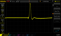
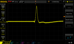
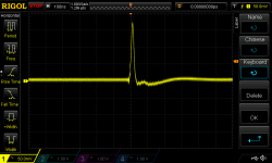
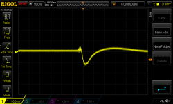
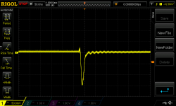
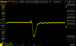
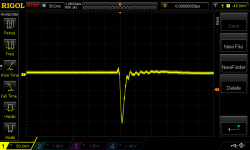
3V3 tests done and all seems okay. The 5V rail seems notably 'slower' than the 12V and the 3V3 similarly so.
Some pics from the 1||4||8R 4.5A <-> 5.0A test. (Scales can be read on the scope shots.)
3V3 tests done and all seems okay. The 5V rail seems notably 'slower' than the 12V and the 3V3 similarly so.
Some pics from the 1||4||8R 4.5A <-> 5.0A test. (Scales can be read on the scope shots.)
Attachments
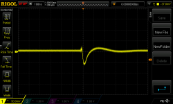
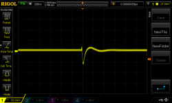
I popped the ferrite beads into the 12V regulator and ran a transient test with 4||8R preload stepping 0.5A. The first 2 pics below are from post 692 when I had previously done this load test. The second two are with the beads in place. They have their minor differences but I suspect adding the beads is not causing a problem. Thoughts?
Attachments

One thing in particular continues to bug me. For the 5V and 3V3 regulators I am using an SPX431AN for the op amp reference. This 0.5% tolerance precision shunt regulator is fed 12V from the 12V regulator board via a 953R resistor (each of which I have checked their resistance). The SPX431AN's internal reference voltage, with Ika = 10mA, has a min of 2.493V, a typical 2.503V and a max 2.515V. It has a wide operating current of 1mA to 150mA. I reckon I am asking it to sink approximately (12-2.5)/953=10mA. Its Vref pin is unconnected (clipped off).
But when I measure the voltage potential at the reg op amp's +input pin I get 2.72V, both with my DMM and with my scope. Perhaps unsurprisingly 5Vout (2 x nominal 1kR resistors for the -input voltage divider) measures 5.45V. 3V3out measures 3.59V and has nominal 316R and 1kR resistors for the -input voltage divider. These are quite large errors.
How can this precision voltage reference deliver such an improper Vref?
PS: should I be tying the Vref pin to the cathode?
Last edited:
PS: should I be tying the Vref pin to the cathode?
Breadboard says "yes"
... ferrite beads ... ran a transient test ... They have their minor differences ...
Since your modification occurs on the "line" side of the voltage regulator, "load regulation" tests are not expected to show any differences.
To test the effectiveness of ferrite beads at improving HF "line regulation", you may want to drive an unused secondary of your power transformer with 200 kilohertz sinewaves, and then observe the amount of 200 kHz at the voltage regulator output. You would do this with, and without, ferrite beads. Of course you run tests at several different high frequencies, perhaps 1K, 2K, 5K, 10K, 20K, 50K, 100K, 200K, 500K, 1MHz, and 2MHz. You will need a reasonably macho power amp to drive this secondary winding.
Good job. Breadboard can also show the Vout versus Iin curve, and confirm that the device indeed does have incredibly low incremental impedance dVout/dIin over the range of input currents that your application might possibly deliver.Breadboard says "yes"
... ferrite beads ... ran a transient test ... They have their minor differences ...Since your modification occurs on the "line" side of the voltage regulator, "load regulation" tests are not expected to show any differences.
Yes. I meant only that adding them didn't seem to incur a cost in the form of ringing (I have added inductance in series with the supply line). Modelling with the Wurth ferrite beads had a large impact on line rejection but caused ringing in transient model tests. Whether these Kemet slip-on beads add much in the way of line rejection I don't know.
Many of the Wurth devices are ferrite-core inductors with several turns of copper wire on a ferrite "pot core" form. This gives higher Q thus greater HF attenuation; but incurs the risk of possibly creating underdamped RLC resonators.
I built and tested a very similar circuit topology this weekend.
NMOS pass transistor: check
AD817 superfast opamp: check
Two stage shunt regulator for LM329 VREF: check
Since I socketed the opamp, it was easy to try out the regulator with lots of different opamps. I plugged in eight opamps spanning a 100-to-1 range of GBW, and the darn thing worked flawlessly every time. With no oscillation or ringing during chop box testing. Woo!
http://www.diyaudio.com/forums/powe...osfet-pass-xitor-1-amp-voltage-regulator.html
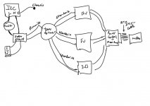
I was thinking about the wiring layout for my overall project and one question popped up when I looked once more at Rod Elliot's material here, particularly Fig 2. Attached is a sketch of my wiring. (I just realised I omitted the transformer screen which is connected to chassis safety earth.)
I don't have any connections from the PSU board grounds to chassis safety earth. (Rod's dark green wire.) Perhaps the mobo connects its ground to the chassis but these points are far from where safety earth is connected. Is this a problem?
I don't have any connections from the PSU board grounds to chassis safety earth. (Rod's dark green wire.) Perhaps the mobo connects its ground to the chassis but these points are far from where safety earth is connected. Is this a problem?
Attachments
Last edited:
Does your mains powered project have any exposed conductive parts?
Then these should be connected to the PE protected Chassis.
If not, then there is no need to electrically connect any of the circuit to Chassis.
Then these should be connected to the PE protected Chassis.
If not, then there is no need to electrically connect any of the circuit to Chassis.
Thanks Andrew. The only 'exposed' high voltage parts would be the very base of the Faston connector tabs on the soft start (i.e. the small bit of the male stud that isn't covered by the insulated female connector).
One other thought. I'm not sure if it matters for this project or for future ones but the transformer secondaries are not marked for polarity. None are being coupled together, but does it ever matter to have the polarities consistent by which I mean the same polarity going to each same part of the bridge rectifier? (If not here I am wondering about other situations where one might have dual full wave bridge rectifiers in parallel.)
........... any exposed conductive parts?.....................
I don't think "high voltage" comes into the analysis.................. The only 'exposed' high voltage parts .................
Any exposed conductive parts. Screw heads included.
Any IC supply pin, resistor leg etc is conductive and exposed. I have test pins and solder pads at each of the regulator outputs. (I'm not sure how one wouldn't have exposed conductive parts if this is the criterion.)
So I should connect each reg board's ground to chassis/safety earth?
So I should connect each reg board's ground to chassis/safety earth?
If by "exposed" you mean accessible when the chassis is assembled then the answer is "no" although the chassis does have typical venting on top and bottom.
I note Rod Elliot's suggestion to "make sure that if the internal circuitry is earthed to the chassis, that this is done as close to the mains earth point as possible. Separating the two earth connections on a chassis can create an internal earth loop that may cause hum when the equipment is connected to something else." So I guess ideally I need to connect the ground of each PCB by direct wire to my safety earth connection on the rear panel. For this project that's a mess of 5 wires (ignoring the mobo PCB which would make its connection via its mounting holes and the chassis parts/connections).
If this safety aspect could be managed via the PCB standoffs to chassis then I guess I should have made a connection from each GND plane to one or more of the standoff screws. I could still do this "manually" and save some wire spaghetti. It would be good to know how to do this properly next time.
- Status
- Not open for further replies.
- Home
- Amplifiers
- Power Supplies
- Adventures with 5A regulated voltage circuits