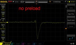
Gulp, that ringing may be significant, esp. since you see it with high current loads but not with lower current loads.
BTW length of wire and inductance to the fixed load resistor is less important, since there is little to none of dI/dt flowing in those wires. All the dI/dt flows in the MOSFET drain.
BTW length of wire and inductance to the fixed load resistor is less important, since there is little to none of dI/dt flowing in those wires. All the dI/dt flows in the MOSFET drain.
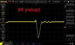
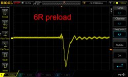
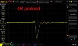
Tests of no-preload through to 4R preload.
I will look at the impact of adding compensation around the op amp (there's none currently) or changing the gatestopper resistor (currently 47R) over the next couple of days.
I will look at the impact of adding compensation around the op amp (there's none currently) or changing the gatestopper resistor (currently 47R) over the next couple of days.
Attachments
Experiment with lesser #waves in the averaging / use "normal" (un averaged) display. Maybe you'll like another setting better.
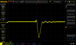
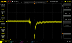
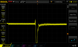
I did a few more tests with the 6R preload as it seemed to exhibit the most pronounced ringing. For reference, the previous scope image is reproduced as Pic 1. (All pics are 20ns/50mV per division and no averaging was used.)
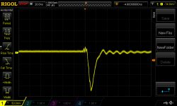
Change 1. I added a 47p cap from op amp -ve input to output. According to my LTspice model this reduces the UGF from c1.2MHz to c360kHz. Modelled phase margin stays the same at around 60 degrees. Scope result is Pic 2.
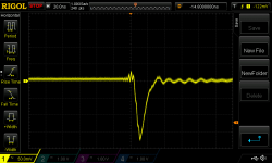
Change 2. I then substantially reduced the size of the regulator MOSFET's gate stopper resistor from 47R to 22R. Modelled UGF increases slightly to c432KHz. Modelled phase margin increases to 78 degrees. Scope result is Pic 3.
I'd say there aren't substantial changes in the output. Pic 2 is mildly improved on Pic 1 but I'd be hard-pressed to say the difference is material.
Change 1. I added a 47p cap from op amp -ve input to output. According to my LTspice model this reduces the UGF from c1.2MHz to c360kHz. Modelled phase margin stays the same at around 60 degrees. Scope result is Pic 2.
Change 2. I then substantially reduced the size of the regulator MOSFET's gate stopper resistor from 47R to 22R. Modelled UGF increases slightly to c432KHz. Modelled phase margin increases to 78 degrees. Scope result is Pic 3.
I'd say there aren't substantial changes in the output. Pic 2 is mildly improved on Pic 1 but I'd be hard-pressed to say the difference is material.
Attachments

If you suspect that the distributed RLC of the (wirewound) preload resistor itself, may be contributing to these post-transient ringing wiggles
Maybe connecting the preload resistor to the transient load tester board is the worst thing you can do, because the transient load tester board ITSELF is noisy (here is recent data). Maybe this stimulates oscillations of the preload resistor and its wiring, which while interesting, are not what you are really looking for: oscillations of the PSU itself.
Maybe you might want to squander GBP 3.00 worth of FastOn female connectors and thick wires, building up a few alternate topologies for harnesses that wire it all together. One possibility that may be useful to try, is shown below.
_
(since the wiggles seem not to be affected by relatively big changes in the regulator's feedback loop)
then you may wish to experiment with different wiring harnesses and different ideas for ways to cable everything together.
Maybe connecting the preload resistor to the transient load tester board is the worst thing you can do, because the transient load tester board ITSELF is noisy (here is recent data). Maybe this stimulates oscillations of the preload resistor and its wiring, which while interesting, are not what you are really looking for: oscillations of the PSU itself.
Maybe you might want to squander GBP 3.00 worth of FastOn female connectors and thick wires, building up a few alternate topologies for harnesses that wire it all together. One possibility that may be useful to try, is shown below.
_
Attachments

Indeed.
Also, I think the following adds weight to the "this is just LCR ringing" in the test setup. I rewired the preload as suggested in post 687. (I had been thinking along similar lines before seeing your post; hopefully that means I have learnt something.) I finally got to do the test this evening.
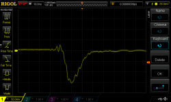
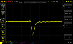
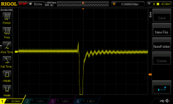
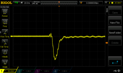
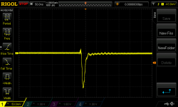
Pic 1 is where I had left off previously i.e. it's the same image as the third in post 686. Pic 2 is the result with the preload connected to the PSU rather than to the Transient Load Tester (post 687) with comparable scope settings. A significant improvement with no change to the PSU itself. Pic 3 is 10ns per division. Pic 4 is 20mV per vertical division (rather than 50mV). Still a little ringing but by far affected by test setup configuration than major changes to the PSU.
I will remove the compensation I added around the op amp and check again but I think I'm ready to give this a clean bill of health. Do you agree?
Also, I think the following adds weight to the "this is just LCR ringing" in the test setup. I rewired the preload as suggested in post 687. (I had been thinking along similar lines before seeing your post; hopefully that means I have learnt something.) I finally got to do the test this evening.
Pic 1 is where I had left off previously i.e. it's the same image as the third in post 686. Pic 2 is the result with the preload connected to the PSU rather than to the Transient Load Tester (post 687) with comparable scope settings. A significant improvement with no change to the PSU itself. Pic 3 is 10ns per division. Pic 4 is 20mV per vertical division (rather than 50mV). Still a little ringing but by far affected by test setup configuration than major changes to the PSU.
I will remove the compensation I added around the op amp and check again but I think I'm ready to give this a clean bill of health. Do you agree?
Attachments


Yes I don't see anything at the 2 ampere level (6R) or the 3 ampere level (4R) that looks like instability. I agree. If "5 amperes" is really just 3 amperes on the 12V supply, I don't think there is any more to do here. Wrap a bow around it and ship it to paying customers!
Encouraged by the foregoing I went ahead and did tests with 6||8 Ohm and 4||8 Ohm preloads. So switching between 3.5A and 4A and switching between 4.5A and 5A. For each of these there are now two of these clunky, long-leaded eBay-from-China power resistors with their long leads.
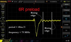
There's still some ringing evident but again I think it is just the load resistors. As Mark noted the frequency is extremely high and unlikely anything to do with the reg feedback loop.
First 3 pics are 6||8R at various resolutions. Second 3 is with 4||8R. The last pic looks at the 0.5A load switching off with a 4.5A preload.
With enormous thanks to Mark , I think I can breathe a sigh of relief and move to the other voltages.
There's still some ringing evident but again I think it is just the load resistors. As Mark noted the frequency is extremely high and unlikely anything to do with the reg feedback loop.
First 3 pics are 6||8R at various resolutions. Second 3 is with 4||8R. The last pic looks at the 0.5A load switching off with a 4.5A preload.
With enormous thanks to Mark
, I think I can breathe a sigh of relief and move to the other voltages.Attachments


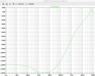
Very nice looking. I doubt whether your final load will be nearly this challenging so I expect your final real-supply-driving-real-load waveforms will be considerably prettier.
Thx. FWIW this is the modelled PSRR. This is without the compensation capacitor around the op amp which I have removed (it did not change the transient waveform). It will be interesting to eventually engage the measurement amplifier to see how it actually does.
Attachments
If you intend to actually TEST what power supply people call "line rejection" (= dVout/dVin), you'll need a way of injecting sinewaves into the input of the voltage regulator. This is difficult because the impedance there is so incredibly low (thanks to many thousands of microfarads of filter capacitance). If you hope to measure -132dB attentuation of 100 Hz sinewave inputs, you'll need a preamp whose gain is at least +60dB, to make something big enough (10mV?) that your oscilloscope can display it.
How big does the input sinewave need to be? The preamp gain is 1000 (60dB) and the end to end attenuation is 4 million (132dB). Thus
How big does the input sinewave need to be? The preamp gain is 1000 (60dB) and the end to end attenuation is 4 million (132dB). Thus
- Vin = Vout * (4E6 / 1E3)
- Vin = 10mV * 4E3
- Vin = 40 volts
Indeed. I merely meant using the c48dB measurement amplifier we built into the 'ATX PSU Control' board and seeing if the line rejection is indeed 'good'. But I have a lot to do before I get to that point (and it of course assumes the amplifier works as intended!)
BTW I did buy a bunch of these ferrite beads to slip over the 0.47R power resistors. I haven't had the balls to try them yet though...
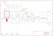
In case anyone else besides me has not memorized the complete schematic including parts values, those resistors are at far left; marked with an arrow in the attached. They are an excellent place to install ferrite beads. Myself, I would bend the resistor lead-out tails asymmetrically so that one horizontal leg was as short as possible (bent right at the resistor body) and the other leg was as long as possible. I'd put a single bead on the long horizontal leg, and stuff the resistor such that the leg with bead was on the downstream (C5) node. But that's just personal taste.BTW I did buy a bunch of these ferrite beads to slip over the 0.47R power resistors. I haven't had the balls to try them yet though...
Attachments
😱
Yes and marked in the attached image. Good point re fitting them. I was going to merely dangle them on the 'post' of the resistor leg but that would leave them potentially leaning on the PCB and they might get quite hot. I will have to dog-leg the resistor leg to keep them elevated.
Still waiting for parts for the 5V/3V3 transient load testers. RS Online in their infinite wisdom decided to send a £6 order in 3 overnight delivery parcels, only two of which arrived on time. Free next day delivery and they do that. Doof!
Attachments
One thing I noticed while doing my first transient tests of the 5V board...
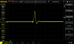
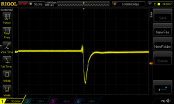
Attached are pics of the response to the load switching off and second the load switching on (at this stage just switching between 0 and 0.53A). Note the difference in vertical scale. No ringing so that's good.
When the load switches off the voltage at the 5V reg output rises some 230mV. Pic 3 in post 678 shows the equivalent waveform for the 12V reg. There the voltage rises quite a bit less (especially when expressed as a percentage change). The reaction to the load coming on is much more comparable (second pic here versus the 4th in post 678).
Adding capacitance to the output of the reg can reduce the amplitude of the reaction when the load comes on. But how does one / can one manage the reaction when the load comes off? Feels like it's similar to a rectifier diode turning off...
Attachments
Last edited:
- Status
- Not open for further replies.
- Home
- Amplifiers
- Power Supplies
- Adventures with 5A regulated voltage circuits