Jens, as you for sure already know, below -100dB distortions every detail matters.
Not related to the Cirrus DAC, for the ADS127L01 ADC I was required to fine tune the timing between MCLK, LRCK and BCLK to bring the distortions to a minimum. There is a deep buried timing diagram in the datasheet, showing that LRCK should come first, followed by the MCLK and BCLK, and the eval board has a weird 10ohm/10pF RC (which is a 400pS delay!) on the MCLK feed. It costed me a few iterations, but it is fine now. I would think there's some asynchronous logic inside that requires a precise timing, but I am speculating.
Without this optimization I could not bring the ADC THD under -106dB (and the THD+N under -100dB) @1KHz/48KHz sampling.
I just tried it with Vp = 3.6 V. It made no difference.
Sorry 🙁. That’s the only thing that the FAE told me via email. I specifically asked about it, though.
No need to be sorry. I appreciate your input.
@syn08
That is definitely a tricky timing! And you're right, every detail matters.
@syn08
That is definitely a tricky timing! And you're right, every detail matters.
Can I say “I don’t care”? You would think the same if you would question yourself why would Cirrus underspec this part, if they would have a chance to match or beat their competitors, at least in some respects.
And are you sure the AKM and ESS parts don’t also “outperform data sheet by significant margin“?
Like everybody else, I’m waiting for the link to those CS43198 measurements.
WRT CS43198 measurements -> Here's a link
Topping D30Pro Review (Balanced DAC) | Audio Science Review (ASR) Forum
Looks pretty good to me.
There is another measurement on ASR which shows even lower but it's
buried in the forum somewhere and I don't have time or inclination to dig it
up.
As suggested by Chris, OOB noise is it's downfall for a measurment DAC.
TCD
Can I say “I don’t care”? You would think the same if you would question yourself why would Cirrus underspec this part, if they would have a chance to match or beat their competitors, at least in some respects.
And are you sure the AKM and ESS parts don’t also “outperform data sheet by significant margin“?
Like everybody else, I’m waiting for the link to those CS43198 measurements.
Here are some more, slightly better. WRT distortion, this must be getting
close to the limit of what can be measured
Measurements of Topping D30Pro DAC | L7Audiolab
One thing I do note with this DAC is the Jitter is really low on *all* inputs, something not often seen. Topping are obviously learning fast.
TCD
Sorry if this has been covered before in this long thread: the AK557x, according to their data sheets, actually have 2 dB better THD+N than the good old AK5394A.
Stephan's Music and Audio Electronics 'Blogalike'
We do know that the AK5394A way outperformed its data sheet, but I wonder how much of the THD+N seen in the AK557x is really aliasing artefacts. After all, their stop band attenuation is only a measly 85 dB as opposed to 120 db in the AK5394A. Can a steep analog filter or digital post-filtering actually result in a new champion for measurements?
Doubtful, I think the actual harmonic distortion is higher. Also, the out-of-band noise is not as flat and rises earlier if I remember correctly. It's probably not worth thinking too hard about the AKM parts unless you have a bunch laying around. They are toast, literally. The best audio ADC you can get right now is either PCM4220/2 or CS5381 still.
Last edited:
Chris, you are correct, I have experimented with an AK5572 evaluation board and it is slightly worse than the AK5394, plus the annoying noise shaping that makes THD+N measurements over 10KHz almost meaningless.
I'm totally confused by the ES9038PRO datasheet. They use the concept of "channel" to identify the 8 digital inputs, the L/R in the PCM stream and also the 8 DAC analog outputs.
So how does one map one of the L or R channels in the PCM stream to all (8) DACs, to get a mono output?
According to the datasheet, register 15 has to get the stereo bit cleared, then registers 38-41 are used to map digital inputs to DACs. But in PCM mode only digital inputs 2,3,4,5 are available (making a total of 8 digital channels) while input 1 reserved for the LRCK. So assuming I am using digital input 2 carrying the PCM L/R channels how do I map all 8 DACs to the same L (or R) digital channel only? Unless I'm missing something, the 38-41 registers documentation talks only about assigning one or more DACs to one full digital input (carrying both L/R for PCM).
Attachments
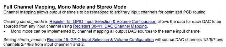
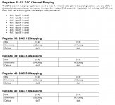
To use 9038Pro for stereo, you have 2 options:
1) Set bit2 in reg #15, you will have 1,3,5,7 outputs at the one channel and 2,4,6,8 at another.
2) Do not set bit 2 in reg #15, and than adjust registers #38-41 as you want, using only 0 or 1 in each their low and high 4 bits.
For example:
#38 = 0x00
#39 = 0x00
#40 = 0x11
#41 = 0x11
With this, outputs 1,2,3,4 will be one channel and outputs 5,6,7,8 - another.
P.S. But I think that the 1st option is optimal for PCB layout.
For volume control, if you do not need to control the balance between L and R - you can set bit 1 in reg #15, and than make both channels volume control by changing only reg #16.
Last edited:
For STEREO it was clear from the very beginning. I was wondering about MONO, one DAC chip (8 analog output channels in parallel) for L, and another DAC chip (8 analog output channels in parallel) for R, all in PCM mode. Is this even possible?
Last edited:
For mono, set all L/R dac pairs to either the L or the R part of the selected digital input signal. The chip has dedicated DATA input pins for PCM. Pick one as the mono digital input.
The GPIO pins may be optionally assigned to act as extra SPDIF inputs.
The GPIO pins may be optionally assigned to act as extra SPDIF inputs.
Sorry, I missed that you wants MONO.
For MONO - do not set bit2 in reg #15, then set all register #38-41 in one chip to zero (0x00) and to 0x11 in the second chip.
For MONO - do not set bit2 in reg #15, then set all register #38-41 in one chip to zero (0x00) and to 0x11 in the second chip.
Chris, you are correct, I have experimented with an AK5572 evaluation board and it is slightly worse than the AK5394, plus the annoying noise shaping that makes THD+N measurements over 10KHz almost meaningless.
You mean slightly worse in terms of THD?
Actually, having seen QA-Matts posts about the prototype QA 402 with PCM4220 driven by an analog oscillator, the PCM also seems to have stellar THD performance (HD2 at -128 dB for +6 dBV input), and unlike the AK5374A, it degrades more gracefully near full scale. What remains is a lowish noise corner:
Sneak Peek: The QA402 - #24 by matt - QuantAsylum Forum
Sorry, I missed that you wants MONO.
For MONO - do not set bit2 in reg #15, then set all register #38-41 in one chip to zero (0x00) and to 0x11 in the second chip.
Thanks, but this doesn't match with the datasheet. First, setting all registers to 0x00 means "map input1" and 0x11 means "map input2" on all DACs. But the datasheet says that "input1" and "input2" refer to the digital inputs (2...5 for PCM) so something is off here. I would expect to have a way to specify through a bitmap in the registers a) the digital input and b) the L/R channel in that input, which doesn't appear to be possible (unless I'm missing something), hence my confusion.
Thanks, but this doesn't match with the datasheet.
Why?
First, setting all registers to 0x00 means "map input1" and 0x11 means "map input2" on all DACs.
Yes, exactly!
But the datasheet says that "input1" and "input2" refer to the digital inputs (2...5 for PCM) so something is off here. I would expect to have a way to specify through a bitmap in the registers a) the digital input and b) the L/R channel in that input, which doesn't appear to be possible (unless I'm missing something), hence my confusion.
Not clear what you mean.
Considering PCM only:
Chip have 4 I2S data lines, 2 channels each, named as DATA2, DATA3, DATA4 and DATA5.
By default, DATA2 - CH1 and CH2 (this line used in stereo).
DATA3 - CH3 and CH4
DATA4 - CH5 and CH6
DATA5 - CH7 and CH8.
As you have only 2 channel stereo, you have only DATA2 (CH1 and CH2).
I2S bus (WCLK, BCLK, DATA) going to both chips.
You need to set all the DAC's output of the 1st chip, to use CH1, setting all registers 38-41 to 0x00.
The 2nd chip you have to set to use CH2 (38-41 = 0x11).
P.S. I understood you point - they used the word "input" instead of the word "channel" in the registers description, and you think that this is related to spdif inputs.
What to do, this is ESS, not TI or AD, and of course not Microchip (the best DS I ever seen, before I stopped to used them, 10 years ago).
And it is good that this is 9038, as I remember, 9018's datasheet had much more errors and typos.
Yes, that's exactly my confusion. So you are saying that in PCM mode "channel 1" and "channel 2" are L/R on digital input 2, right? Then "channel 3" and "channel 4" are L/R on digital input 2, etc...
Thanks!
Thanks!
You mean slightly worse in terms of THD?
Actually, having seen QA-Matts posts about the prototype QA 402 with PCM4220 driven by an analog oscillator, the PCM also seems to have stellar THD performance (HD2 at -128 dB for +6 dBV input), and unlike the AK5374A, it degrades more gracefully near full scale. What remains is a lowish noise corner:
Sneak Peek: The QA402 - #24 by matt - QuantAsylum Forum
Yes, AK5572 is slightly worse (about 2 dB) in terms of THD. THD+N in particular @1KHz is better by the same amount, but this is not really relevant due to noise shaping in the AK5572.
The guy(s) who decided to implement noise shaping for audio in order to feed the SNR war (since there is no real benefit in doing this, beyond the numbers in the datasheet) should be hanged in public.
Yes, that's exactly my confusion. So you are saying that in PCM mode "channel 1" and "channel 2" are L/R on digital input 2, right? Then "channel 3" and "channel 4" are L/R on digital input 2, etc...
Thanks!
You are welcome.
- Home
- Design & Build
- Equipment & Tools
- ADCs and DACs for audio instrumentation applications