Happy New Year 🙂
Starting the new year and decade playing a bit with DSP.
Have bought a Sure DSP and programmer board, and gotten familiar with SigmaStudio.
Time to do my own 😉
Would highly appreciate a review for any mistakes or misunderstandings I might have made, by someone much more experienced in ADAU1701 design than myself.
I can make PCB design available if interested ... when I get that far 😉
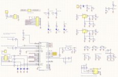
Design based on ADAU1701 obviously, and NCS2632 to allow for pop free operation.
The output is enabled by a voltage monitor, TCM809TENB713.
I have included 3 general use pots for control, and 3 LEDs for especially peak indicators.
Output 0 and 1 are additionally run through a 10k log pot, for use with e.g. a sub amplifier directly, or my coming party box a la "Soundboks"
There is an extension port which is intended to be used for additional or alternative DAC / Codec. I have not included the I2C signals though, which is otherwise the normal for e.g. FreeDSP ... can't really see the use ... but correct me if I'm wrong on this.
/Baldin
Starting the new year and decade playing a bit with DSP.
Have bought a Sure DSP and programmer board, and gotten familiar with SigmaStudio.
Time to do my own 😉
Would highly appreciate a review for any mistakes or misunderstandings I might have made, by someone much more experienced in ADAU1701 design than myself.
I can make PCB design available if interested ... when I get that far 😉
Design based on ADAU1701 obviously, and NCS2632 to allow for pop free operation.
The output is enabled by a voltage monitor, TCM809TENB713.
I have included 3 general use pots for control, and 3 LEDs for especially peak indicators.
Output 0 and 1 are additionally run through a 10k log pot, for use with e.g. a sub amplifier directly, or my coming party box a la "Soundboks"
There is an extension port which is intended to be used for additional or alternative DAC / Codec. I have not included the I2C signals though, which is otherwise the normal for e.g. FreeDSP ... can't really see the use ... but correct me if I'm wrong on this.
/Baldin
Attachments
No reconstruction filters on the DACs? IIRC the ADAU1701 datasheet shows both active and passive implementations with the active more preferable (IMO).
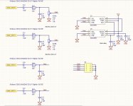
Output filters are made around the NCS2632s. Each contain 2 opamp drivers, and the filter is build around these as suggested in the tne ADAU1701 data sheet.
The nice thing about NCS2632 is that it also holds a switched capacitor supply to generate a negative rail, and an enable pin to ensure all caps are fully charged before the output is turned on, creating a hopefully pop free operation.
The nice thing about NCS2632 is that it also holds a switched capacitor supply to generate a negative rail, and an enable pin to ensure all caps are fully charged before the output is turned on, creating a hopefully pop free operation.
Hi Baldin
Happy New Year to you as well!
Maybe I'm just crossed up by the variable names, but it looks to me like you have the Outx and VOUTx connections to the pots reversed. The PWM outs should probably go to the CW terminal rather than the wiper.
There must be a DC reference for the output buffer/LPF's, U6 and U8; happily the NCS2632's are designed to eliminate the need for coupling caps, both incoming and outgoing, by generating its own -Vss. I still have some studying to do on the data sheets, but a resistor from each Pin 6 to its corresponding PWM out, U4 pins 43 through 46 should probably do it. Trouble is, that will alter the LPF behavior in ways that I'm not smart enough to predict. You may need a separate buffer for the level shifting; happily (again!) the 2632's are only US$0.71 each.(DigiKey)
The input caps, C14 and C16, are larger than I would use -- 2.2 or 4.7uF is usually plenty with an 8k resistor in series. The input protection belongs on the other side of the current-limiting resistor, though. A pair of Schottky's (chosen for relatively low capacitance) to each supply rail is typical; that saves having to account for the usually very high capacitance of MOV's and Varistors.
Your LPF is a Sallen-Key variant -- a practical, hard-working design -- but I haven't seen a 47:15 ratio between frequency-determining elements before. It certainly isn't a Butterworth response -- those are typically a 2.0 or 2.2 ratio. Also, you may want to consider polystyrene or mica or metalized film rather than NPO. The latter is OK temperature-wise, but is on the lossy side for a filter.
If you're really worried about pop suppression, design one detection circuit and send the signal to every IC that you want to control. Each IC having its own resistive divider (and yielding a slightly different threshold) is a troubleshooting nightmare when something goes wrong.
Somebody smarter than me might know a good reason for an Under Voltage protect feature on a 600 ohm line driver, but I can't think of one. Also, a series 75 or 100R is usually enough for output short-circuit protection in such cases. I wouldn't be willing to pay the 6dB gain 'penalty' (that will result with 604R in that position) if a proper 600-ohm-terminated line is driven.
What a fun, interesting project. Congrats for tackling it.
Cheers,
Rick
PS - sorry I didn't see your Post#3 before clicking away on this.😉
Last edited:
Hi Rick
Thanks for feedback.
You are totally right about the output pot. Have changed it in the new file.
Maybe a bit different labeling would be good … changed to DAC_OUT for the output from the ADAU1701, for clarity 😉
The Sallen Key filter is based on the opamps as unity buffers.
What do you mean by DC reference for U6 and 8?
Input caps for U6 and U8 I think is needed. They are doing the level shifting.
Cap size … yes 47uF is a bit over the top, and 4,7uF would probably be better in many ways .. not least taking less time to char initially, but also requiring less space on PCB. But I would like to keep the Fs quite low especially for the subwoofer use (not having multiple high pass filters on e.g. 10Hz on top of each other).
As for ESD protection, I think I need to research a bit more. Maybe something like this:
[Resolved] INA137: Differential line receiver input protection - Audio forum - Audio - TI E2E support forums
with 100pF direct on input and a TVS diode at the ADAC pins 2 and 4 after the 8k resistors.
The under voltage protection should actually detect the missing power, but it seems like a little double action together with the Enable pin on the NCS2632! Was thinking that you could mayby bust use the UVP function to eliminate pop … but from the data sheet this is not clear.
Also I have been thinking on whether the WB function will work?
In a setup whare you have direct power input to the board from say a wall plug PSU, it will work well … as unplugging the power input will totally remove the 12V and will therefore turn Q1 off and WB will go high immediately.
In a setup where the board is powered from same supply as e.g. the power amp, the input power will not turn instantly.
But you can maybe “tune” this little circuit to change state, when the “12V” input falls below e.g. 7V. Will sim it … will only be a matter of the right value for R2 I think ….
Regarding the 600 ohm on output … you are right …. But in say 10k it is not really a problem. A 100 ohm resistor would require a 20nF cap for same feq … a bit large for a NP0!
As to NP0, Mica or polystyrene …. I thought NP0 is actually the best? ….. but disputed by analog HIFI nerds 😉 …. Maybe I’m wrong ……. Do you have something scientific on this?
Also found that a diode was missing in the 12V input to allow for better detection on power loss.
/Baldin
Attachments
You're welcome!
A unity-gain Sallen-Key is perfectly OK, but with matching resistor values, the damping/frequency response is set by the capacitance ratio -- 47:15 is going to be (probably should've LTSpice'd this before risking foot-in-mouth disease, but I'll leave that to you) very under-damped. Anything higher than about 2.2:1 is rare in audio use.
Without a DC reference (or maybe 'DC path to ground' would be more accurate), an LPF has no incentive to center itself in the available signal range (whether its 0 - 3.3V or +/-3V). If you keep the level-shifting caps, they'll need to have a DC load to the new signal ground. Keep it 10x or so less than the resistor values used in the LPF to avoid disrupting its action. (Another useful simulation project 😉)
** Wait just a gol-darn minute **
Sorry I didn't see this sooner: Consider moving the gain pots to the U6/8 outputs. That solves the interaction issue with the LPF input.
The point about layers of 10Hz Fs's is a good one but, how many are you going to have? Whatever the source is might have one at its output, the preamp probably has at least one, and the power amp may have one at its input. That's at least three already; whether this device adds two or one more probably won't change much. Plus, remember that 0.33Hz isn't really just 9.7Hz below 10Hz -- it's 30 times lower in the terms that frequency understands.
Good catch on the INA137/ESD note from the TI forum. But I'm still fuzzy on the point of the 100pF before the resistor.
Seems like .. maybe you're being seduced by the UVP and EN stuff. 😉 There aren't any parts here that will hurt themselves by trying to operate on a low supply. And each IC with its own EN pin -- that's what our portable-everything/battery-powered design world has become -- for those pieces of kit that must conserve every few dozen microamps everywhere they can. Even so, if you simply can't resist, please consolidate all the EN's and drive them with one 'detection' circuit. Having separate RC time constants on so many parts is just begging for power supply sequencing nightmares. You might build one that works great; if you build 20, even 1% resistors and (very expensive) 2% capacitors won't save you from problems with 4 or 5 of 'em. Especially with 2 separate regs for analog and digital supplies for the 1701. Those adorable little LP5907's are great (thanks for introducing me to them😉) but are more than the design needs. You could just tie all the EN's active and try to worry less about power cycle pops; or maybe control just the ones on the last stages.
The WB function is completely beyond me today -- plenty of study still waiting for me on that sweet ADAU1701.
If you really want power loss detection there's an easy way to do it using the Base-Emitter junction of a sturdy PNP to detect the supply current rather than voltage. Did I see correctly that the 78M05 is only a sub-reg for the 3.3V guys? If so there's plenty of room to do it either way.
Can't figure what you mean by the '100R output resistor requiring a 20nF cap'. After all there may be up to a few hundred pF of cable capacitance to drive, and we don't want treble rolloff or gain change by cable length or power amp input impedance. Also don't understand the reason for the outputs to have 3.3nF capacitors and 47K resistors, either .. so something else for me to learn.
There's really no single best capacitor for all applications -- different dielectrics have different properties over temperature, DC bias, frequency of AC bias, practically everything. NPO's have good stability over temperature and time, but have higher loss and leakage and are not available in big enough values for most audio uses. There should be plenty of info online.
I'm gonna get back to work studying that 1701.😉
Regards,
Rick
Last edited:
Oopsy doodle! There's still something major I missed/forgot 😱😱 --
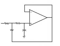
On the Sallen-Key LPF's the node between the resistors has to connect to the capacitor whose other leg comes from the op amp output, not ground. The cap whose other leg is ground must have its signal side connected to the node between the +input and the 2nd resistor. The current way looks to me like it'll oscillate.
I'll try to cobble up a quicky sketch here in a minute ..
Rick
Attachments
Last edited:
Not so concerned about the filter ... 3. order at ca. 100kHz
Think the DC path made by changing from buffer/unity to a gain stage x1 adding 2 resistors (one from out to +in and one from +in to gnd).
Having a DC over the pot is not a good idea I think as it will make noise when being operated.
I think you are reading the UPV wrongly. It is no a protection as such but a way to turn the output off.
I was hoping for someone with experience with ADAU1701 to take a look and comment on the digital design before I make the PCB
/Baldin
The PCM5102a DAC may be worth a look as an alternative method to achieve a pop free output, it also uses a charge pump and has auto mute built in, uses 3 lines i2s. Output is slightly lower at 2.1VRMS. One advantage is that it would free up the onboard dacs for signal metering if desired.
Re ADAU1701, have you taken a look at the 1452/1466, approx 40X the processing power (20,000 taps FIR) with built in ASRC and SPDIF I/O. Can be bought as a core board if soldering is an issue, would increase the price though plus would need ADC's on the inputs, pcm1802 is a simple option.
Re ADAU1701, have you taken a look at the 1452/1466, approx 40X the processing power (20,000 taps FIR) with built in ASRC and SPDIF I/O. Can be bought as a core board if soldering is an issue, would increase the price though plus would need ADC's on the inputs, pcm1802 is a simple option.
Ups ... I stand corrected, you are right about the filter implementation ... don't know what I did there .... !
Good catch
Good catch
Filter schematics updated
Components need to be re-calculated for the filter section as the opamp now have a gain to calculate in.
But first things first, need to have the right topology and all the components in the right places
Components need to be re-calculated for the filter section as the opamp now have a gain to calculate in.
But first things first, need to have the right topology and all the components in the right places
Attachments
Hi SubSonic
Yes have been looking at the PCM5102a as well. Think you suggested this in another thread before. Not a bad solution. But had hoped to make something even more simple. The NCS2632 turns out to become complex as well!
The intention was to keep it as simple as possible for the first implementation! .... seems it is getting complex pretty fast 🙂
ADAU1452 would be a natural next step 😉
I had hoped to find a full codec chip with pop free operation and with a bit better THD performance than the built in ADC/DAC.
I know the MiniDSP HD uses the Cirrus CS42528, but I think this also does not offer pop free operation.
I have a MiniDSP, and even that (as far as I can see on the PCB) they have tried to implement a mute function ... there is a big pop when turning on and off!!!
With a big sup with hundreds of W, this is not really the best 😉
Baldin
Sorry I wasn't more help with the ADAU1701 -- but I'm gonna keep studying -- and thanks much for introducing me to it.
The reason the filter damping matters is that even with Fc @100kHz the impulse response in the audible range may not be what we usualy seek.
Now .. to pull and study your Post #11 schem ... and then sidetrack myself (again😉) with the 1452/1466 tip/suggestion (which might just hit a different nail on the head for me -- one that brought me into your neighborhood to begin with! 😱).
Cheers
Wow. I don't see how the ADAU1452 could produce a simpler implementation -- 195 page data sheet vs 52 for the 1701, 6x the clock frequency, and no legs complicating rework -- despite about the same USD $11 price AND Automotive Qualified.
Wow. Now I really have some homework to do ...
Rick
Wow. Now I really have some homework to do ...
Rick
Last edited:
My current project is to use some ebay pcm5102a and pcm1802 boards with a adau1466 core board, all going to be mounted on perfboard. I'm going to bypass the on-board I/O filters as they use ceramic caps and also include RF and antialiasing filters on the inputs. Also planning passive balanced outs. Currently have it wired up with one ADC and a DAC, so far so good.
Another option for reducing pop and click is the MAX9892 ....... only needs a mute signal .....
It's a shunt device so should have minimal impact on sound ...
It's a shunt device so should have minimal impact on sound ...
Another nifty part you've introduced me to. 😀
Its designed to connect right at a headphone jack, though. With 30R series feed and 16 ohm headphones it attenuates 38dB. It would probably be all you need, but build it first using just the 2632's EN -- maybe it'll satisfy just as well .. or better!
Then you wouldn't have to fight the manual soldering nightmare of the bump package or buy some little darling adapters.
Last edited:
I'm still reading up on the ADAU1701, but noticed something else I should've noticed sooner:
Changing the output filter from Unity Gain is a good idea -- ADC input full-scale is 2 Vrms (if you change the series resistors to the 18k shown in the 'protos' shown on pages 49, 50 and 51 of Rev.C of the data PDF) while DAC output full-scale is 0.9Vrms -- a 7dB loss.
But the circuit change you described has a typo: The resistive divider HAS to be from Output to the '-', inverting input.
And it gives both 'reward, and penalty' .. The gain can be handy, of course -- 6dB will result if the resistors are equal -- but I don't recommend it! Damping is no longer controlled by the ratio of the capacitors: Higher gain results in lower damping. Before you start ordering parts it might be worth checking out "Equal component value Sallen-Key filters". Sams used to publish "Active Filter Cookbook" by Don Lancaster and I highly recommend it. Mine is over 40 yrs old now and I still refer to it once in a while. It has just enough math that you can accomplish what you want even if you don't have an engineering degree.
Best Regards
Time to get on with this project.
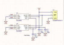
To keep it very simple in this first go, I have decided to give the MAX9892 "Shunt Mode Audio Click-and-Pop Eliminator" a go. Distortion should be very low, so only the very small physical size of the components are a bit scary 😉
Changed regulators to LM317MSTT3, again for simplicity.
A bit unsure whether I have exposed enough pins for further experiments with external DAC like pcm5102a or a full codec. My extension port is called "Expansion1" on the schematics.
Output filters changed for a simple RC network.
Anything missing?
PCB will be 75 mm x 65 mm to fit on the back of a plain "flight case connection dish"
Attachments
- Home
- Source & Line
- Digital Line Level
- ADAU1701 based DSP for sub or 2 way