Hi aparatus,
do you have any super reg PCBs to sell?
Could you post the reverse side and the schematic?
do you have any super reg PCBs to sell?
Could you post the reverse side and the schematic?
Hi Andrew,
At the moment I don't have any...I have given away for free all I have. But I could easily produce any quantity you or anyone else needs. The problem is that I don't have a remote idea how to organise payment and other bits and pieces.
And I don't have a dig. camera to take a image of the reverse side, sorry...I just use a friend with it to take a image for occasion.
Yes, I do have the original files in Eagle, but I intent to do same cosmetical changes...and those PCBs are my first job done with dammn thing. What a pain to learn! I even have to translate same japanese site to learn how to make new componet
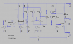
Oh, schematic is the same as per W. Jung "Improved poz/neg voltage regulators...", but I have used a 2SC2240/2SA970 thermaly coupled with rectangular LED diode for current source, and CRC filter is 2200uF-6R2-2200uF/35V or 3300uF-6R2-3300uF/25V.
I'm rapidy geting old , forgot to mension a small capacitor near by opamp... it is a something like 22pF cap for compesating NE5534 for unity gain (or is it NE5532?)
 , if you are on a limited $$$.
, forgot to mension a small capacitor near by opamp... it is a something like 22pF cap for compesating NE5534 for unity gain (or is it NE5532?), if you are on a limited $$$.Hi,
The 5532 (dual) is already unity gain stable.
yes, the 5534 needs 22pF comp cap for unity gain.a small capacitor near by opamp... it is a something like 22pF cap for compesating NE5534 for unity gain
The 5532 (dual) is already unity gain stable.
This is a Eagle3D images of the real thing, and before you ask, I did use a 6 pieces of 47uF/35V tantalum as well as 100uF/25V Panasonic FM caps. Those disc caps nearby main filter elcos are nice Philips "orange drops" 100n film caps in my case, but I could't render them. Nice little bugger this Eagle3d thing, isn't it?
http://img.photobucket.com/albums/v58/aparatusonitus/W.jpg
http://img.photobucket.com/albums/v58/aparatusonitus/W.jpg
aparatusonitus said:
Not in my text book...in fact I see it as a very simple, elegant and extremely well behaved circuit... two tumbs up for Scott Wurcer.
If I could lend my hands to Philips BC846(B)S, BC857(B)S, BC850, 860 as well as BCP54/55/56 and BCP51/52/53 I'd start to buid it immediately. With these transistors, I think it will not be expensive to build at all, if you can deal with SMD parts.
Just found that Buerklin stock this transistors and a little shop in my hometown as a distributor, so I'll start to creating new devices in Eagle, 'cos there is none dual transistors in SOT363 package...what a pain
I don't believe any discrete version of AD797 can close to the performance of integrated AD797. For one simple thing, can you make your discrete opamp with 0.1mV Vos over the common-mode range?
Yes, you can make -3dB frequency at 600kHz with ideal current source. If you put any real transistor on it, you amp will oscillate. Think about what is your Avo!?
I have measured some of AD797 with AP2700. And I found that the distortion of AD797 is virtually null. All THD+N number come from the thermal noise of the opamp.

kwkam said:I don't believe any discrete version of AD797 can close to the performance of integrated AD797. For one simple thing, can you make your discrete opamp with 0.1mV Vos over the common-mode range?
Yes, you can make -3dB frequency at 600kHz with ideal current source. If you put any real transistor on it, you amp will oscillate. Think about what is your Avo!?
I have measured some of AD797 with AP2700. And I found that the distortion of AD797 is virtually null. All THD+N number come from the thermal noise of the opamp.
With LM394 at input or equivalent, I believe this low offset is possible.
Best comparing to discrete using 600R load, >5kHz, 10V (pk) OP swing and some real gain of say 30.
You will see distortion then.
cheers
Terry
In the case of using LM394. I don't know is it still discrete opamp. Instead of Vbe mis-match in differential pair. Discrete opamp is hard to make systematic offset as low as 0.1mV
And that is reason why people make 741 years ago.
And that is reason why people make 741 years ago.
AD797: what a nice scheme!
Hello,
I was attracted by the elegance of the AD797 schematic (well, the simplified schematic only is available) and so I decided to reproduce it on LTSpice.
Here my interpretation, maybe one day I will make it as discrete one:
any opinion?
Hello,
I was attracted by the elegance of the AD797 schematic (well, the simplified schematic only is available) and so I decided to reproduce it on LTSpice.
Here my interpretation, maybe one day I will make it as discrete one:
any opinion?
Attachments
Hello,
I was attracted by the elegance of the AD797 schematic (well, the simplified schematic only is available) and so I decided to reproduce it on LTSpice.
Here my interpretation, maybe one day I will make it as discrete one:
any opinion?
Differential input stage -> folded-cascode VAS with shunt compensation -> diamond buffer output stage.
The novelty is the current mirror of the VAS is bootstrapped. It should benefit its open-loop bandwidth.
As the vas stage has no current gain, it may lack gain as standalone power amp. For an audio amplifier, you want at least 23dB gain after closing the loop. Plus 50dB negative feedback at 1KHz.
Last edited:
D
Deleted member 550749
Made this , Circuit working, it has only one problem, whenever I remove input signal,getting dc9v plus out and when connecting signal from phone jack it's become 1.8mv offset and works, why without signal or any input connection getting DC out and circuit not working 🤔 any fix?AD797 Clone people! Who can make a better one?
I think I manage to bit you lineup😀 ...at least my sim tells me so
Below you'll find a circuit and FFt diagram at 1kHz and 20kHz (output at 1Vpp, load 600R)

I am disappointed Lineup never published his own schematic.
🙂
Would not happen today ...
🙂
Would not happen today ...
D
Deleted member 550749
AD797 is very good, but it is not unique.
For exanple AD847 and AD8021 uses the same folded cascode idea.


For exanple AD847 and AD8021 uses the same folded cascode idea.
- Home
- Amplifiers
- Solid State
- AD797 Clone people! Who can make a better one.